background image

20

03/13424999502

Chain drive for ventilation EM S Tandem AC

Scope of delivery EM S Tandem AC 

2 x ventilation chain drives with a 4-wire connection cable
4 x 0,75 mm², length 2,4 m and power cable on the master drive
3 x 0,75 mm², length = 8 m.

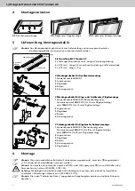
V1 Montagezubehör für Dachfenstermontage

1

 Schwenkkonsole SBEM/DF

2

 Lagerbuchsen

3

 Flügelbock

4

 Bolzen

5

 Sicherungssplint

V2 Montagezubehör für Kipp- oder Drehfenster Flügelmon-
tage

1

 Schwenkkonsole SBEM/KF0 (flächenbündig) oder 

   Schwenkkonsole SBEM/KF10 (für 10 mm Flügelaufschlag)
   oder SBEM/KF15 (für 15 mm Flügelaufschlag)

2

 Lagerbuchsen

3

 Flügelbock

4

 Bolzen

5

 Sicherungssplint

V3 Montagezubehör für Kippfenster Rahmenmontage

1

 Schwenkkonsole SBEM/R0 (flächenbündig) oder 

   Schwenkkonsole SBEM/R10 (für 10 mm Flügelaufschlag) 
   oder SBEM/R15 (für 15 mm Flügelaufschlag)

2

 Lagerbuchsen

3

 Flügelbock

4

 Bolzen

5

 Sicherungssplint

6

 Flügelwinkel

40

Ø 5,2

40

15

8 24

40 15

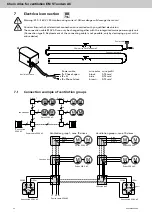
Master

Slave

B

C

connection

cable

power cable

Master drive 

Slave drive

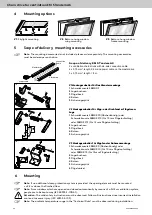
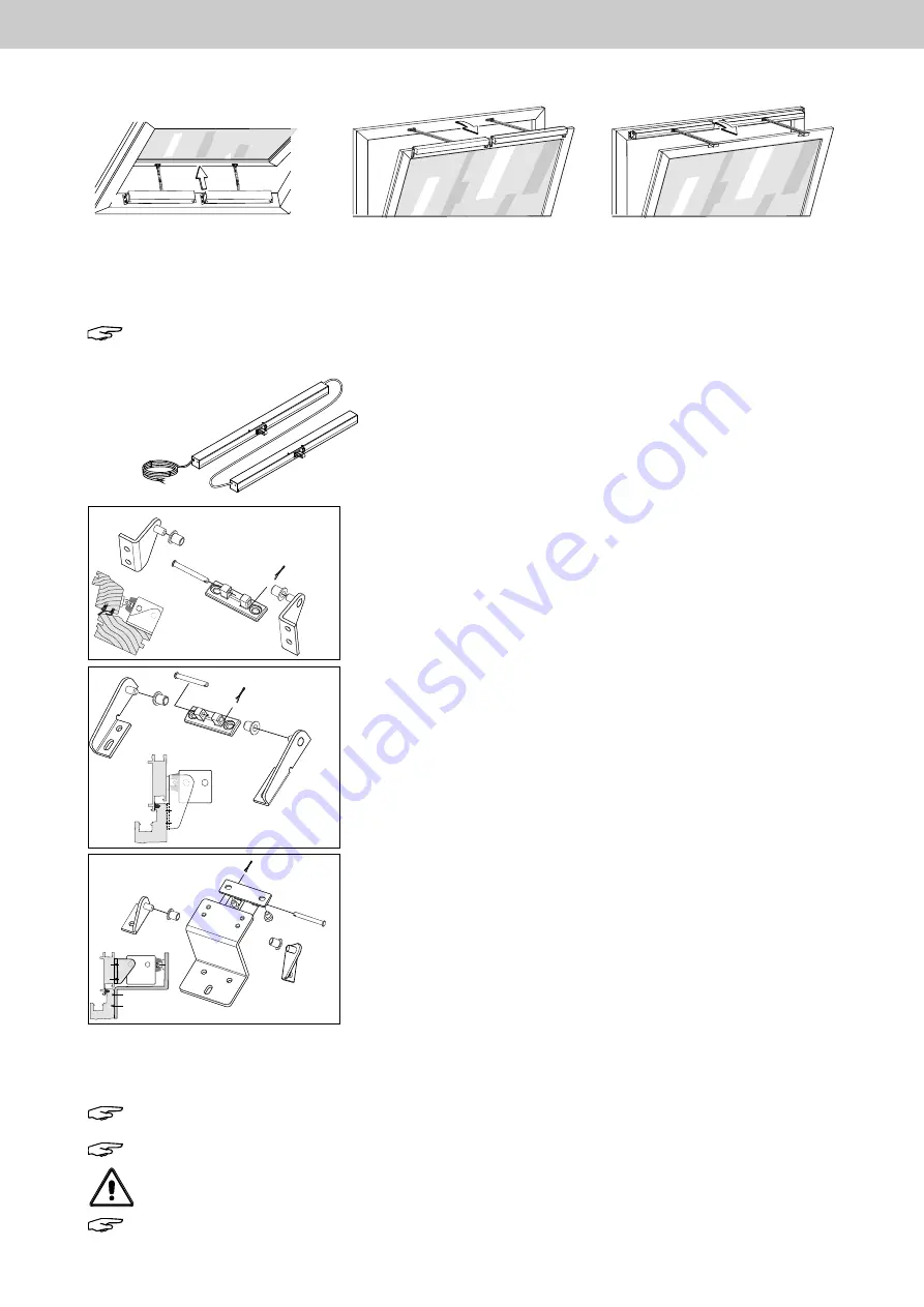
Mounting options

V1

: Skylight mounting  


V2

: Bottom-hung window 


V3

: Bottom-hung window


       wing mounting 


       frame mounting

Scope of delivery, mounting accessories

 Note: 

The mounting accessories is not included, please order separately. The mounting accessories 


must be ordered per each drive.

B1

A

C1

B1

A

C1

B1

A

C1

1

1

2

2

3

4

5

1

2

2

3

4

5

1

2

3

4

5

V1

V2

V3

6

1

1

2

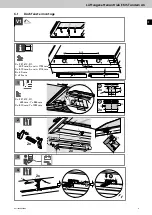
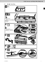
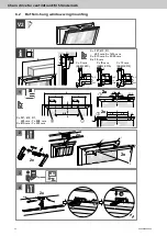
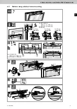
6 Mounting


Note:

 If no additional clamp protection system is provided, the opening element must be mounted


> = 2.5 m above the finished floor.


Note:

 From windows which are opened and closed automatically by means of a SHE or ventilation system,


people are to be kept away (IEC 60335-2-103/A1).


Attention

: The valid safety instructions must be observed. Follow all instructions since incorrect installation


can lead to severe injury. (IEC 60335-2-103).


Note:

 The ambient temperature range in the "Technical Data" must be observed during installation.

Summary of Contents for EM S Tandem AC

Page 1: ...D GB Lüftungskettenantrieb EM S Tandem AC Technische Information und Bedienungsanleitung Chain drive for ventilation EM S Tandem AC Technical information and operating instruction 2 14 ...

Page 2: ...ftungskettenantrieb EM S Tandem AC 1 Allgemeines und Sicherheit 2 Produktbeschreibung 2 1 Besonderheiten 3 Technische Daten 4 Montagevarianten 5 Lieferumfang Montagezubehör 6 Montage 6 1 Dachfenstermontage 6 2 Kippfenster Flügelmontage 6 3 Kippfenster Rahmenmontage 7 Elektrischer Anschluss 7 1 Anschlussbeispiel Lüftungsgruppen 8 Maßzeichnung 9 Diagramm Druckkraft Kettenausstellweite Hub 3 5 5 6 8 ...

Page 3: ...n auf einwandfreie Funktion zu prüfen und die Prüfungen und ihre Ergebnisse zu dokumentieren Betrieb Ein sicherer Betrieb ist gewährleistet wenn die zulässigen Nenndaten und die Vorgaben gemäß den War tungshinweisen dieser Dokumentation und der ergänzenden Informationen des Herstellers eingehalten werden Fehlbetrieb Wird bei einer Installation Wartung Prüfung etc eine Fehlfunktion festgestellt sin...

Page 4: ...hmen oder Brandschutzbehörden festlegen Leitungen für Kleinspannungen z B 24 V DC sind getrennt von Niederspannungsleitungen z B 230 V AC zu verlegen Flexible Leitungen müssen so verlegt sein dass sie im Betrieb weder abgeschert verdreht noch abgeknickt werden können Energieversorgungen Steuereinrichtungen und Verteiler dosen müssen für Wartungsarbeiten zugänglich sein Die Leitungsarten längen und...

Page 5: ...llläufermotor S Laufgeschwindigkeit 10 5 mm s Tandemlastabschaltung im Gehäuse des Masterantriebes integriert Integrierter Überlastschutz Automatisches Abschalten beim Erreichen der Endpositionen Endposition AUF über eingebauten Endschalter Endposition ZU über elektronische Lastabschaltung Dichtschluss über elektronisch definierten Anpressdruck Äußere Teile korrosionsbeständig Ausstellmechanik mit...

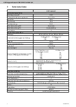
Page 6: ...inwärts öffnend in Abhängigkeit der Hublänge Mind Flügelhöhe in mm Hublänge in mm für Kippfenster einwärts 445 327 590 419 725 511 855 603 1100 810 Maße L x H x T Hub 327 419 511 603 mm 820 x 40 x 40 mm Hub 810 mm 1011 x 40 x 40 mm Gewicht in Abhängigkeit der Hublänge Gewicht in kg Hublänge in mm ca 4 0 327 ca 4 2 419 ca 4 4 511 ca 6 0 603 ca 7 0 810 Anschluss und Betrieb Anschluss und Verbindungs...

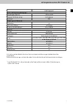
Page 7: ...der Zyklen nach 1 Stunde EM S Tandem AC Einbau und Umgebungsbedingungen Umgebungstemperatur 10 C bis 60 C Geeignet für Außenmontage nicht geeignet Schutzart IP 20 Zulassungen und Nachweise CE konform ja TÜV und UL Prüfung auf Anfrage Emissions Schalldruckpegel LpA 70 dB A Material Gehäuse Aluminium Ausstellmechanik Edelstahlkette Endkappen Zinkdruckguss in Antriebsfarbe Farbe pulverbeschichtet Wei...

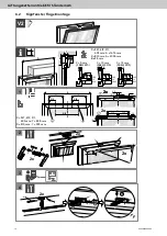
Page 8: ...10 mm Flügelaufschlag oder SBEM KF15 für 15 mm Flügelaufschlag 2 Lagerbuchsen 3 Flügelbock 4 Bolzen 5 Sicherungssplint V3 Montagezubehör für Kippfenster Rahmenmontage 1 Schwenkkonsole SBEM R0 flächenbündig oder Schwenkkonsole SBEM R10 für 10 mm Flügelaufschlag oder SBEM R15 für 15 mm Flügelaufschlag 2 Lagerbuchsen 3 Flügelbock 4 Bolzen 5 Sicherungssplint 6 Flügelwinkel B1 A C1 B1 A C1 B1 A C1 1 1 ...

Page 9: ...ntage V1 Montage am Dachfenster 1 k k Y Y 2 Y 2 20 k 28 23 18 Y 2 4 3 20 3 2 1 1 1 2 2 1 15 2x 2x 2x 2x 2x 20 X 327 419 511 603 mm A min 1732 mm X 810 mm A min 2114 mm B 40 mm C 23 mm A C B A 2 X 327 419 511 603 mm Y 844 mm X 810 mm Y 1035 mm 1 1 2 2 3 1 1 2 2 3 3 4 5 5 4 ...

Page 10: ...Y 2 Y 2 40 20 18 5 33 5 2 3 18 3 15 18 5 15 18 5 4 3 A Y Y 2 Y A 2 Y 2 2x 2x 2x 2x 2x 2x 2x 18 3 18 3 18 3 X 327 419 511 603 mm A 1676 mm X 810 mm A 2058 mm B 38 mm X 327 419 511 603 mm Y 808 mm X 810 mm Y 999 mm 1 1 2 2 3 4 5 1 1 2 3 4 5 5 4 6 2 Kippfenster Flügelmontage C 0 mm C 10 mm C 15 mm SBEM KF0 SBEM KF10 SBEM KF15 ...

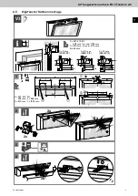
Page 11: ...5 15 15 12 15 Y Y 2 Y 2 15 12 30 15 15 B C A 4 3 3 2x 2x A Y Y 2 Y A 2 Y 2 2x 2x 2x 2x 18 3 18 3 18 3 C 0 mm C 10 mm C 15 mm SBEM R0 SBEM R10 SBEM R15 1 1 1 1 2 2 2 6 6 3 3 4 4 5 5 X 327 419 511 603 mm A min 1732 mm X 810 mm A min 2114 mm B 46 mm X 327 419 511 603 mm Y 844 mm X 810 mm Y 1035 mm 6 3 Kippfenster Rahmenmontage ...

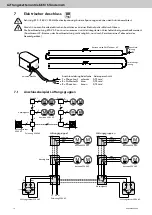
Page 12: ...e Lüftungstaster 230V AC 3 2 1 A A AnschlussleitungAderfarbe Aderquerschnitt 1 Phase Lauf schwarz 0 75 mm 2 Nullleiter N blau 0 75 mm 3 Phase Lzu braun 0 75 mm Verbindungs leitung Kettenantrieb EM S Tandem AC Anschluss leitung Knickschutztülle 7 Elektrischer Anschluss Achtung 230 240 V 50 Hz Wechselspannung Andere Spannungen können den Antrieb zerstören Vorsicht Lassen Sie alle elektrischen Anschl...

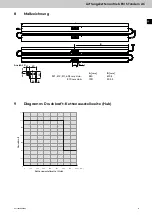
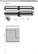
Page 13: ...ichnung 9 Diagramm Druckkraft Kettenausstellweite Hub X Ansicht X B 40 24 40 15 40 15 8 Ø 5 2 A F N 0 0 100 200 300 400 500 600 100 200 300 400 500 600 700 800 L mm A mm B mm 327 419 511 603 mm Hub 820 410 5 810 mm Hub 1011 505 5 Druckkraft Kettenausstellweite Hub ...

Page 14: ...S Tandem AC Page Content 1 General information and safety instructions 2 Product description 2 1 Special features 3 Technical datas 4 Mounting options 5 Scope of delivery mounting accessories 6 Mounting 6 1 Skylight mounting 6 2 Bottom hung window wing mounting 6 3 Bottom hung window frame mounting 7 Electrical connection 7 1 Connection example of ventilation groups 8 Drawing 9 Diagram Pressing fo...

Page 15: ...tests and the results thereof should be documented Operation Safe operation is guaranteed if the acceptable rated values and guidelines regarding maintenance informa tion stated in this documentation as well as supplementary information provided by the manufacturer are followed Malfunction If a malfunction is identified in the course of installation maintenance inspection etc immediate action shou...

Page 16: ...rglary and attack alarm systems If necessary cable types must be defined in conjunction with the local approval bodies power supply companies or fire safety authorities Cabling for extra low voltages e g 24 V DC is to be laid separately from low voltage line e g 230 V AC Flexib le cables must be laid in such a way that they cannot be sheared off twisted or snapped during operation Power supplies c...

Page 17: ...motor S speed 10 5 mm s Tandem power cut off integrated in the case of the master drive Integrated overload protection Automatic switch off when end position is reached End position OPEN via integrated limit switch End position CLOSE via electronic power cut off Seal closure relief using electronically defined pressing force Corrosion free external elements Opening mechanics with stainless steel c...

Page 18: ...inwards opening depending on the stroke length Minimum sash height in mm Stroke length in mm for bottom hung window inwards 445 327 590 419 725 511 855 603 1100 810 Dimensions Stroke 327 419 511 603 mm 820 x 40 x 40 mm Stroke 810 mm 1011 x 40 x 40 mm Weight depending on the stroke length Weight in kg stroke length in mm ca 4 0 327 ca 4 2 419 ca 4 4 511 ca 6 0 603 ca 7 0 810 Circuit connections and...

Page 19: ...g mechanics stainless steel chain End caps zinc die casting Colour powder coated white RAL 9016 or silver grey RAL 9006 other RAL colours on request Scope of delivery see page 20 Accessories see page 20 Halogen free no Silicon free no RoHS compliant yes Trouble free and safe operation is only warranted when used in conjunction with appropriate manufacturers control unit Request a technical conform...

Page 20: ...ck 4 Bolzen 5 Sicherungssplint 6 Flügelwinkel 40 Ø 5 2 40 15 8 24 40 15 Slave B C connection cable power cable Master drive Slave drive 4 Mounting options V1 Skylight mounting V2 Bottom hung window V3 Bottom hung window wing mounting frame mounting 5 Scope of delivery mounting accessories Note The mounting accessories is not included please order separately The mounting accessories must be ordered...

Page 21: ...Dachfenster 1 m m k k Y Y 2 Y 2 20 k 28 23 18 Y 2 4 3 20 3 2 1 1 1 2 2 1 15 2x 2x 2x 2x 2x 20 X 327 419 511 603 mm A min 1732 mm X 810 mm A min 2114 mm B 40 mm C 23 mm A C B A 2 X 327 419 511 603 mm Y 844 mm X 810 mm Y 1035 mm 1 1 2 2 3 1 1 2 2 3 4 5 5 4 6 1 Skylight mounting ...

Page 22: ... 2 Y 2 40 20 18 5 33 5 2 3 18 3 15 18 5 15 18 5 4 3 A Y Y 2 Y A 2 Y 2 2x 2x 2x 2x 2x 2x 2x 18 3 18 3 18 3 X 327 419 511 603 mm A 1676 mm X 810 mm A 2058 mm B 38 mm C 0 mm C 10 mm C 15 mm SBEM KF0 SBEM KF10 SBEM KF15 X 327 419 511 603 mm Y 808 mm X 810 mm Y 999 mm 1 1 2 2 3 4 5 1 1 2 3 4 5 5 4 6 2 Bottom hung window wing mounting ...

Page 23: ...2 15 15 15 12 15 Y Y 2 Y 2 15 12 30 15 15 B C A 4 3 3 2x 2x A Y Y 2 Y A 2 Y 2 2x 2x 2x 2x 18 3 18 3 18 3 C 0 mm C 10 mm C 15 mm SBEM R0 SBEM R10 SBEM R15 1 1 1 1 2 2 2 6 6 3 3 4 4 5 5 X 327 419 511 603 mm A 1732 mm X 810 mm A 2114 mm B 46 mm X 327 419 511 603 mm Y 843 mm X 810 mm Y 1035 mm 6 3 Bottom hung window frame mounting ...

Page 24: ...itch 230V AC 3 2 1 A A Anti kink sleeve Power cable Connection cable Chain drive EM S Tandem AC 7 1 Connection example of ventilation groups Power cable wire color wire profil 1 Phase Lopen black 0 75 mm 2 N blue 0 75 mm 3 Phase Lclose brown 0 75 mm 7 Electrical connection Warning 230 240 V 50 Hz alternating current Other voltage will damage the motor Caution Ensure that all electrical connections...

Page 25: ...Tandem AC A mm B mm Stroke 327 419 511 603 mm 820 410 5 Stroke 810 mm 1011 505 5 X View X B 40 24 40 15 40 15 8 Ø 5 2 A F N 0 0 100 200 300 400 500 600 100 200 300 400 500 600 700 800 L mm 8 Drawing 9 Diagram Pressing force Stroke Stroke Pressing force ...

Reviews: