background image

19

03/13424999487

Safety instructions


Disposal: Packaging is to be disposed of 


appropriately. Electrical equipment is to be 

disposed of at recycling collection points for scrap 
electrical and electronic equipment. The Electrical and 
Electronic Equipment Act relating to disposal of electrical 
equipment does not apply in this instance. Rechargeable 
and single-use batteries are to be disposed of in line with 
§ 12 of the Battery Ordinance (BattV), either via the 
manufacturer or at an appropriate collection point. 
Electrical equipment and batteries must not be disposed 
of with household waste.

Compatibility: When putting together a system consisting 
of various devices made by different manufacturers, the 
system compatibility must be tested and approved by the 
constructor to ensure safe function during operation.
Equipment modification to achieve compatibility must be 
authorised by the manufacturer.

Conformity: This confirms that the equipment complies 
with the recognised rules of engineering. For electrical 
equipment a declaration of EC conformity can be 
requested from the manufacturer. Note: if the equipment 
(e.g. drive unit) is part of a machine in terms of the
Machinery Directive 2006/42/EC, this does not render the 
supplier/contractor exempt from informing the customer 
with regard to the necessary installation instructions, 
labelling, documentation and certificates relevant to this 
directive.

Guarantee: The ZVEI “Green Supply Conditions” are 
taken as agreed. The guarantee period for material supply 
is 12 months. Any intervention with the equipment or 
system that is not authorised by the manufacturer will 
result in invalidation of liability, guarantee and service.

Liability: Product changes and settings may be modified 
without advance notice. Illustrations are not binding. No 
liability will be held for contents despite maximum care 
being taken.

Electrical safety

Wiring and electrical connections must only be done by 
an electrician. The appropriate laws, specifications and 
standards must be observed, such as the directive relating 
to fire safety of conduit installations (MLAR / LAR /
RbALei), VDE 0100 (specifications for high-voltage 
circuits up to 1000 V), VDE 0815 (installation cables 
and wiring), VDE 0833 (fire, burglary and attack alarm 
systems). If necessary, cable types must be defined in 
conjunction with the local approval bodies, power supply 
companies or fire safety authorities.

Cabling for extra-low voltages (e.g. 24 V DC) is to be laid 
separately from low-voltage line (e.g. 230 V AC). 
Flexible cables must be laid in such a way that they 
cannot be sheared off, twisted or snapped during 
operation. Power supplies, control units and junction 
boxes must be accessible for maintenance work.
Cabling types, lengths and cross-sections are to comply 
with technical guidelines.

  Before work is carried out on the system, the 


mains current and emergency power supply 

(eg. rechargeable batteries) is to be disconnected from 
all-poles and secured to prevent accidental switch-on. 
Never operate the drive units, control units, operator 
elements and sensors on supply voltage and 
connections in such a way as to contravene the guidelines 
in the operator manual. There is a risk of fatal injury, 
and it can cause components to be destroyed!

Mechanical safety

Falling window casements: Window casements are to be 
mounted in such a way that even if one of the suspension 
elements fails, the design prevents the unit from falling or 
moving in an uncontrolled way, e.g. by double 
hanging, security stay, safety catch. Please note: to 
prevent obstruction/falling of the window, the security stay/
safety catch must be compatible with the intended open-
ing span and mechanism of the window. See also the 
directive for power-operated windows, doors and gates 
(BGR 232) and the ZVEI brochure "RWA Update No. 3, 
power-operated windows".

Fittings and fixing material: any fixing materials required or 
supplied with the product must be adapted to the building 
and load, and if necessary supplemented.


Crush and shear points: 


Power-operated windows, doors and gates: 

Any crush and shear hazard areas, for instance between 
the casement and frame or skylight and base, must be 
secured against trapping using appropriate measures to 
prevent injury. See also the directive for power-operated 
windows, doors and gates (BGR 232) and the ZVEI 
brochure " RWA Update No. 3, power-operated windows".

Accident prevention regulations and industrial 
compensation laws: For works to, on or in a building or 
part thereof, the appropriate accident prevention
regulations (UVV) and industrial compensation laws 
(BGR) are to be observed.

Environmental conditions: The product must not be 
knocked, dropped, or exposed to vibration, moisture, 
aggressive vapours or harmful environments, unless the 
manufacturer has authorised one or more of these
environmental conditions.

Locking drive RM mini EasyDrive/2

Summary of Contents for RM mini EasyDrive/2

Page 1: ...D GB Riegelantrieb RM mini EasyDrive 2 Technische Information und Bedienungsanleitung Locking drive RM mini EasyDrive 2 Technical information and operating instruction 2 16 ...

Page 2: ...cherheitstechnik GmbH Co KG Trifte 89 D 32657 Lemgo Lieme info STG BEIKIRCH de www STG BEIKIRCH de Anwendungsbereich Besonderheiten Sicherheitshinweise Lieferumfang Anwendungsbeispiel Montage Elektroanschluss Manuelle Setbildung Maßzeichnung Technische Daten 3 3 4 6 6 7 8 12 13 14 Seite Riegelantrieb RM mini EasyDrive 2 Inhalt ...

Page 3: ...erbindlich Riegelantrieb RM mini EasyDrive 2 Anwendungsbereich 24 V DC Verriegelungsantrieb zur Kombination mit Kettenantrieben der Serie EasyDrive 2 Zur Verriegelung von größeren Fenstern über den innenliegenden Fensterbeschlag Besonderheiten extrem kompaktes Aluminiumgehäuse für die profilintegrierte Montage speziell zur Kombination mit EasyDrive 2 Kettenantrieben EasyDrive 2 Elektronik mit eing...

Page 4: ...ieren Betrieb Ein sicherer Betrieb ist gewährleistet wenn die zulässigen Nenndaten und die Vorgaben gemäß den War tungshinweisen dieser Dokumentation und der ergänzen den Informationen des Herstellers eingehalten werden Fehlbetrieb Wird bei einer Installation Wartung Prüfung etc eine Fehlfunktion festgestellt sind unverzüglich Maß nahmen zur Behebung einzuleiten Reparatur und Instandsetzung Defekt...

Page 5: ...trennt von Niederspannungsleitungen z B 230 V AC zu verlegen Flexible Leitungen müssen so verlegt sein dass sie im Betrieb weder abgeschert verdreht noch abgeknickt werden können Energieversorgungen Steu ereinrichtungen und Verteilerdosen müssen für Wartungs arbeiten zugänglich sein Die Leitungsarten längen und querschnitte gemäß den technischen Angaben ausführen Vor Arbeiten an der Anlage sind di...

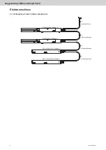
Page 6: ... und Verbindungsleitung ist 6 adrig und in folgenden Längen erhältlich 1 5 m 3 1 m 5 1 m 8 1 m Anwendungsbeispiel Der RM mini EasyDrive 2 Riegelantrieb ist für den verdeckt liegenden Einbau im Blendrahmenprofil eines Fensters gedacht Die Einbaulage des Antriebes ist vom Fenstersystem und dessen Profil abhängig Riegelantrieb RM mini EasyDrive 2 RM mini EasyDrive 2 profilintegriert in Kippfenster ei...

Page 7: ...reißen und Ausfräsungen vornehmen Achtung Bei der Auswahl des Einsatzortes sind die zulässigen Umgebungstemperaturen zu berücksichtgen Den Antrieb im Rahmen befestigen Achtung Materialschäden Verwenden Sie nur für Ihr Profil geeignete Befestigungsschrauben Zuvor den elektrischen Anschluss ab Seite 8 herstellen Den RM mini EasyDrive 2 Riegelantrieb in die nach Montage zeichnung angebrachte Ausfräsu...

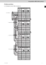
Page 8: ... EasyDrive 2 CDi EasyDrive 2 Anschlussleitung Verbindungsleitung 6 4 RM mini EasyDrive 2 Klemm stelle Bezeichnung 1 24 V 0 V 2 0 V 24 V 3 Bus A 4 Bus B 5 24 V 0 V 6 0 V 24 V 7 Bus A 8 Bus B CDi EasyDrive 2 Klemm stelle Bezeichnung 1 24 V 0 V 2 0 V 24 V 3 Bus A 4 Bus B 5 24 V 0 V 6 0 V 24 V 7 Meldekontakt 8 Meldekontakt Anschlussleitung Verbindungsleitung ...

Page 9: ...V 24 V 7 Meldekontakt 8 Meldekontakt CDi EasyDrive 2 Antrieb 1 Klemm stelle Bezeichnung 1 24 V 0 V 2 0 V 24 V 3 Bus A 4 Bus B 5 24 V 0 V 6 0 V 24 V 7 Meldekontakt 8 Meldekontakt Elektroanschluss 2 x CDi EasyDrive 2 und 1 x RM mini EasyDrive 2 1 2 3 4 5 6 7 8 5 6 7 8 1 2 3 4 1 2 3 4 5 6 7 8 CDi EasyDrive 2 Antrieb 1 CDi EasyDrive 2 Antrieb 2 RM mini EasyDrive 2 Anschlussleitung Verbindungsleitung V...

Page 10: ... 2 und 2 x RM mini EasyDrive 2 5 6 7 8 1 2 3 4 1 2 3 4 5 6 7 8 5 6 7 8 1 2 3 4 1 2 3 4 5 6 7 8 CDi EasyDrive 2 Antrieb 1 CDi EasyDrive 2 Antrieb 2 RM mini EasyDrive 2 Antrieb 1 RM mini EasyDrive 2 Antrieb 2 Anschlussleitung Verbindungsleitung Verbindungsleitung Verbindungsleitung 6 4 4 4 ...

Page 11: ...2 Antrieb 2 Klemm stelle Bezeichnung 1 24 V 0 V 2 0 V 24 V 3 Bus A 4 Bus B 5 24 V 0 V 6 0 V 24 V 7 Bus A 8 Bus B CDi EasyDrive 2 Antrieb 2 Klemm stelle Bezeichnung 1 24 V 0 V 2 0 V 24 V 3 Bus A 4 Bus B 5 24 V 0 V 6 0 V 24 V 7 Meldekontakt 8 Meldekontakt CDi EasyDrive 2 Antrieb 1 Klemm stelle Bezeichnung 1 24 V 0 V 2 0 V 24 V 3 Bus A 4 Bus B 5 24 V 0 V 6 0 V 24 V 7 Meldekontakt 8 Meldekontakt Ansch...

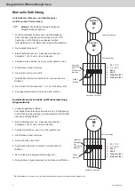
Page 12: ...rieb 1 Verbindungsleitung entfernen Anschließend den einzelnen Antrieb mit 24 V DC Spannung in AUF Richtung versorgen zum Beispiel ein AUF Befehl über einen Lüftungstaster 2 Eine Drahtbrücke für ca 1 Sekunde zwischen den Kontakten 1 24 V und 3 Bus A stecken 3 Antrieb bleibt stehen wenn er vorher gefahren ist 4 Drahtbrücke wieder entfernen 5 Der Antrieb fährt kurz AUF 6 Anschließend fährt der Antri...

Page 13: ...13 03 13424999487 Riegelantrieb RM mini EasyDrive 2 Maßzeichnung 35 368 10 118 10 17 74 5 6 6 12 5 15 11 22 106 22 25 ...

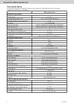
Page 14: ...ische Eigenschaften Hublänge 18 mm Druckkraft 600 N Zugkraft 600 N Zuhaltekraft max 2000 N Laufgeschwindigkeit ca 7 8 s bei Nennbetrieb 600N mind Flügelhöhe bei Hubweite Maße L x H x T 368 x 25 x 35 mm Gewicht ca 0 5 kg ohne Anschlussleitung Anschluss und Betrieb Anschlussleitung nicht im Lieferumfang enthalten elektr Anschluss 8 polige Steckschraubklemme Anschluss siehe technische Dokumentation A...

Page 15: ...g Spannungsversorgung so zu konfigurieren daß die Motorspannung nach einer vorgegebenen Zeit Abhängig von den Hublängen und Laufgeschwindigkeit der Antrie be abgeschaltet wird In Abhängigkeit der verwendeten Zentralen ist bei der Dimensionierung der Energieversorgung und zur Dimensionierung der Kabelquerschnitte der Motorzuleitung mit erhöhten Strömen im Anlaufmoment zu rechnen Ein funktionssicher...

Page 16: ...chnik GmbH Co KG Trifte 89 D 32657 Lemgo Lieme info STG BEIKIRCH de www STG BEIKIRCH de Area of application Special features Safety instructions Scope of delivery Application Examples Mounting Electrical connection Manually set formation Drawing Technical datas 17 17 18 20 20 21 22 26 27 28 Page Content Locking drive RM mini EasyDrive 2 ...

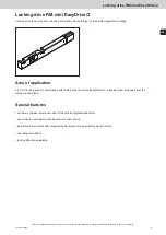
Page 17: ...fittings for the profile integrated mounting Area of application 24 V DC locking drive for combination with chain drives the series EasyDrive 2 For locking larger windows about the inside window fitting Special features extremely compact aluminum case for the profile integrated assembly especially for combination with EasyDrive 2 chain drives EasyDrive 2 electronics with integrated power switch of...

Page 18: ... guaranteed if the acceptable rated values and guidelines regarding maintenance information stated in this documentation as well as supplementary information provided by the manufacturer are followed Malfunction If a malfunction is identified in the course of installation maintenance inspection etc immediate action should be taken to rectify the problem Repair and maintenance Defective equipment m...

Page 19: ...ith the local approval bodies power supply companies or fire safety authorities Cabling for extra low voltages e g 24 V DC is to be laid separately from low voltage line e g 230 V AC Flexible cables must be laid in such a way that they cannot be sheared off twisted or snapped during operation Power supplies control units and junction boxes must be accessible for maintenance work Cabling types leng...

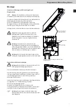
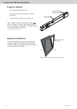
Page 20: ...ng The Easy Drive 2 Connection cable is 6 core and available in lengths of 1 5 m 3 1 m 5 1 m 8 1 m Application Example The RM mini EasyDrive 2 locking drive is designed for concealed installation in the frame profile of a window Installation position and fastening of the drive depend on the window system and its profile RM mini EasyDrive 2 profile integrated in turn window inward Connector housing...

Page 21: ... and with the actual spacing of your motor before you mark the respective holes and make cutouts Attention The permissible ambient temperatures are to be taken into consideration when choosing the installation site Fasten the drive in the frame Attention Material damage Only use the fastening screws suitable for your profile Previously on page 22 prepare the electrical connection Place the RM mini...

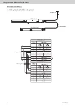
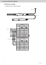
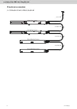
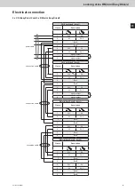
Page 22: ...4 V 7 Bus A 8 Bus B CDi EasyDrive 2 Clamp Description 1 24 V 0 V 2 0 V 24 V 3 Bus A 4 Bus B 5 24 V 0 V 6 0 V 24 V 7 signal contact 8 signal contact power cable connection cable Electrical connection 1 x CDi EasyDrive 2 and 1 x RM mini EasyDrive 2 1 2 3 4 5 6 7 8 5 6 7 8 1 2 3 4 RM mini EasyDrive 2 CDi EasyDrive 2 power cable connection cable 6 4 ...

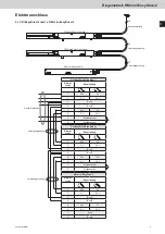
Page 23: ...ntact CDi EasyDrive 2 drive 1 Clamp Description 1 24 V 0 V 2 0 V 24 V 3 Bus A 4 Bus B 5 24 V 0 V 6 0 V 24 V 7 signal contact 8 signal contact power cable optional connection for signal contact connection cable connection cable Electrical connection 2 x CDi EasyDrive 2 and 1 x RM mini EasyDrive 2 1 2 3 4 5 6 7 8 5 6 7 8 1 2 3 4 1 2 3 4 5 6 7 8 CDi EasyDrive 2 drive 1 CDi EasyDrive 2 drive 2 RM mini...

Page 24: ...Di EasyDrive 2 and 2 x RM mini EasyDrive 2 5 6 7 8 1 2 3 4 1 2 3 4 5 6 7 8 5 6 7 8 1 2 3 4 1 2 3 4 5 6 7 8 CDi EasyDrive 2 drive 1 CDi EasyDrive 2 drive 2 RM mini EasyDrive 2 drive 1 RM mini EasyDrive 2 drive 2 power cable connection cable connection cable connection cable 6 4 4 4 ...

Page 25: ...ni EasyDrive 2 drive 2 Clamp Description 1 24 V 0 V 2 0 V 24 V 3 Bus A 4 Bus B 5 24 V 0 V 6 0 V 24 V 7 Bus A 8 Bus B CDi EasyDrive 2 drive 2 Clamp Description 1 24 V 0 V 2 0 V 24 V 3 Bus A 4 Bus B 5 24 V 0 V 6 0 V 24 V 7 signal contact 8 signal contact CDi EasyDrive 2 drive 1 Clamp Description 1 24 V 0 V 2 0 V 24 V 3 Bus A 4 Bus B 5 24 V 0 V 6 0 V 24 V 7 signal contact 8 signal contact power cable...

Page 26: ...gle drives 1 Remove the connection cable Then provide the individual drive with 24 V DC voltage in the UP direction for example an OPEN command via a vent switch 2 Place a jumper wire for about 1 second between contacts 1 24 V and 3 Bus A 3 The drive stop if he went before 4 Remove the jumper again 5 The drive go short UP 6 Subsequently the drive retract and make a zero crossing 7 The drive is rec...

Page 27: ...27 03 13424999487 Locking drive RM mini EasyDrive 2 Drawing 35 368 10 118 10 17 74 5 6 6 12 5 15 11 22 106 22 25 ...

Page 28: ...length 18 mm Pressing force 600 N Tractive force 600 N Nominal clamping force approx 2000 N Speed of operation ca 7 8 s at rated for operati 600N Min casement height at stroke length Dimensions L x H x T 368 x 25 x 35 mm Weight ca 0 5 kg without power cable Circuit connections and operation Power and connection cable not included in delivery Electr connections 8 pole plug in screw terminal Connect...

Page 29: ...st to configure the control panel power supply with switch off the motor volta ge after a certain time period depending on stroke length and speed of operation When dimensioning the power supply and the cable cross sections for the supply lines to the motors as a function of the control panels used the increased currents associated with start up torques must be taken into account Trouble free and ...

Reviews: