DESCRIPTION
The EZ-Path Modular Floor Grid System is designed to
facilitate the installation of multiple high-volume EZ-Path
Series 44+ pathways through floors. The rugged, galvanized
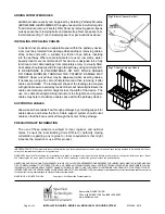
steel grid frame assembles quickly and easily and is bolted
over pre-formed openings in concrete floors.
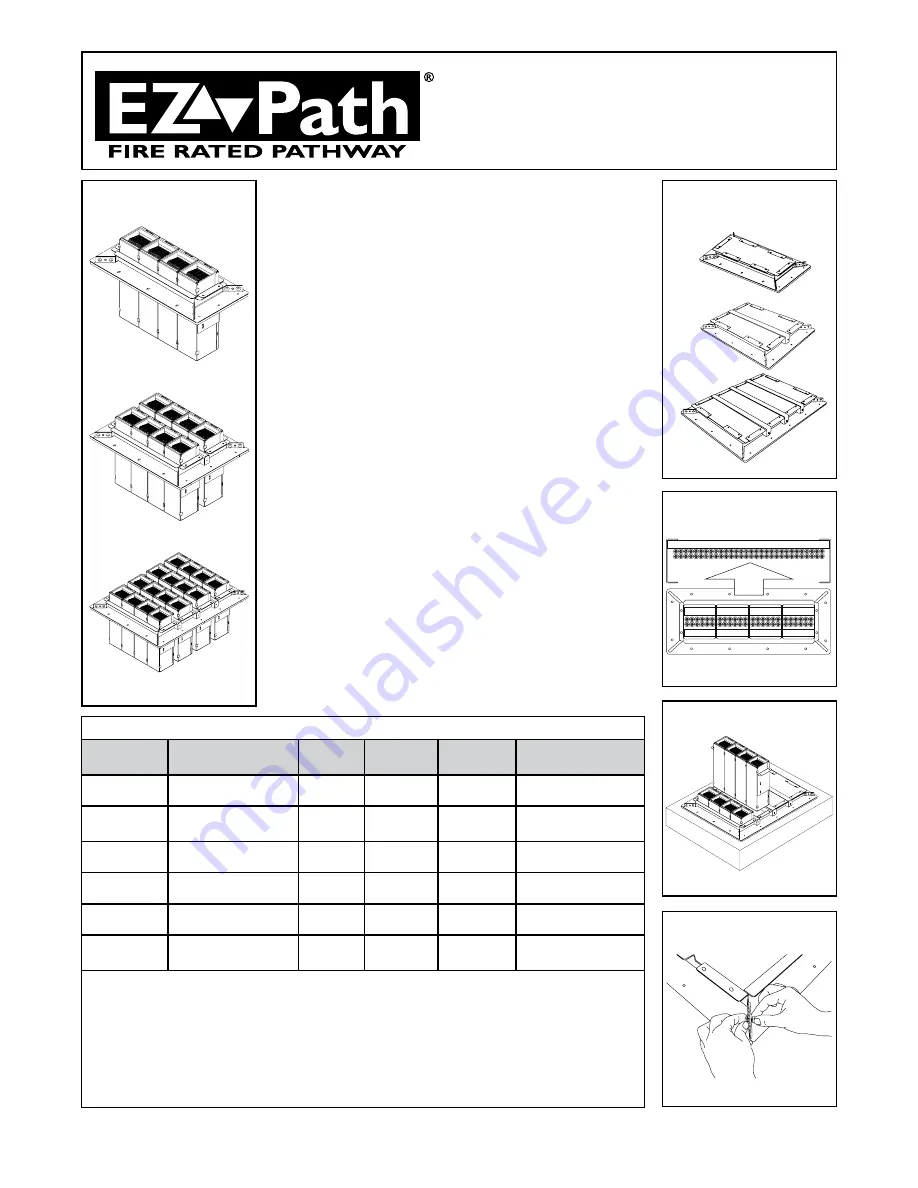
Pathways in banks of four, form modules that easily install
through slots provided in the Grid. Grid sizes are available
to accommodate one (1) , two (2), or four (4) modules. All
grid sizes may be purchased as complete kits including
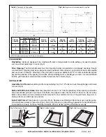
pathway modules (Fig 1). Multi-slot grids may be purchased
with blank firestop filler panels (Fig 2) allowing modules to
be purchased and installed at a later date as needed.
Components: See Table A below.
NOTE: Anchor fasteners are required to secure grid frame
to floor and must be purchased separately. 3/16” x 1-1/4”
concrete screws are recommended. See Table A for the
number of fasteners required for the model chosen.
Floor grids (EZG444, EZG844 & EZG1644) include firestop
filler panels to seal slots. Pathway module(s) (EZD444MBS
or EZD444MBS2) must be purchased separately.
For additional information regarding components see the
following Product Data Sheets:
• EZ-Path Series 44+ Fire Rated Pathway
• Spec-Seal® Intumescent Composite Sheet
INSTALLATION GUIDE
SERIES 44+ MODULAR FLOOR GRID SYSTEM
TABLE A: Components
Model
Pathway Module
(Four Pathways)
Firestop
Panels
Panel
Clips
Space Bar
Assembly
Concrete Fasteners
Not Included
EZDG444S /
EZDG444S2
One (1) Included
NA
NA
NA
12
EZDG844S /
EZDG844S2
Two (2) Included
NA
NA
One (1)
12
EZDG1644S /
EZDG1644S2
Four (4) Included
NA
NA
Three (3)
16
EZG444
One (1) Purchase
Separately
One (1)
Four (4)
NA
12
EZG844
Two (2) Purchase
Separately
Two (2)
Eight (8)
One (1)
12
EZG1644
Four (4) Purchase
Separately
Four (4)
Twelve
(12)
Three (3)
16
Grid Frame Assembly:
Four Piece Grid Frame with gaskets
Four (4) 1/4-20 x 1/2 Hex Bolts, Four (4) 1/4-20 x 1/2 Hex Nuts
Pathway Module:
Four (4) Series 44 Pathways
One (1) RH Hanger Bracket, One (1) LH Hanger Bracket
Four (4) 1/4-20 x 1/2 Hex Bolts, Four (4) 1/4-20 x 1/2 Hex Nuts
Spacer Bar Assembly:
One (1) Spacer Bar
One (1) Spacer Strap
One (1) Spacer Strap Gasket
Two (2) 1/4-20 x 1/2 Hex Head Clamp Bolts
Page 1 of 4
INSTALLATION GUIDE • SERIES 44+ MODULAR FLOOR GRID SYSTEM
ZIS1049 0916
Fig 1: Complete Kits with
Pathway Modules
EZDG444S & EZDG444S2
EZG1644
EZDG844S & EZDG844S2
EZDG1644S & EZDG1644S2
Fig 2: Grids with Firestop Filler
Panels (No Pathway Modules)
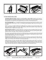
Fig 3: Grid Orientation
Fig 4: Installing on Raised Curb
Fig 5: Assemble Grid
EZG844
EZG444


