Page 4 of 4
INSTALLATION GUIDE • SERIES 44+ MODULAR FLOOR GRID SYSTEM
ZIS1049 0916
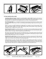
Fig 16: Install Spacer Bar Bolt
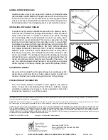
Fig 17: Adding Pathway Module
ADDING PATHWAY MODULES
Additional cable capacity can be gained by installing Pathway Modules
(EZD444MBS or EZD444MBS2) through unused slots in multi-slot grids.
To add module, remove Firestop Filler Panel by removing panel clips as
well as spacer bar clamping bolts and panel strap. Remove spacer bar.
Install module (Fig 17) and reinstall spacer bar per instructions above.
INSTALLING OR PULLING CABLES
A resilient liner provides an adjustable seal within the pathway device.
Liner must be protected from damage while adding or removing cables.
Wrap cable ends with a suitable low friction tape before inserting
into the pathway. Where cable lubricants are used, low solids, water-
based products are recommended. This device is designed to be fully
functional at all cable loadings from completely empty to visually filled,
and cables should easily slide through the pathway using minimal effort.
IF RESISTANCE IS ENCOUNTERED, DO NOT FORCE CABLES
OR CABLE BUNDLES THROUGH THE PATHWAY. DAMAGE MAY
RESULT. Upper curved liner may be depressed when inserting cables,
if necessary, using a flat, smooth implement and then removing it after
cables are installed. The rectangular shape of the loading area coupled
with gentle pressure exerted by resilient liners will naturally distribute the
cables at a relatively uniform height across the width of the device. The
use of a cable dressing/combing instrument to straighten and organize
cables may help to maximize usable space within the pathway device.
SUPPORTING CABLES
Allow slack where cables flow through pathways by providing support for
cables above and below the floor. Cable support system should orient
cables so that the flow is vertical through the center of the pathways.
PRECAUTIONARY INFORMATION
The use of these products is subject to local, regional, and national
codes. Consult the local Building Code Official or Authority Having
Jurisdiction regarding any regional or local requirements that might
influence the selection or use of this product.
IMPORTANT NOTICE: All statements, technical information, and recommendations contained herein are based upon testing believed to be reliable, but the ac-
curacy and completeness thereof is not guaranteed.
WARRANTY: Specified Technologies Inc. manufactures its goods in a manner to be free of defects. Should any defect occur in its goods (within one year), Speci-
fied Technologies Inc., upon prompt notification, will at its option, exchange or repair the goods or refund the purchase price.
LIMITATIONS AND EXCLUSIONS: THIS WARRANTY IS IN LIEU OF ALL OTHER REPRESENTATIONS EXPRESSED OR IMPLIED (INCLUDING THE IMPLIED WARRAN-
TIES OF MERCHANTABILITY OR FITNESS FOR USE) AND UNDER NO CIRCUMSTANCES SHALL SPECIFIED TECHNOLOGIES INC. BE RESPONSIBLE FOR ANY
INCIDENTAL OR CONSEQUENTIAL PROPERTY DAMAGE OR LOSSES. PRIOR TO USE, THE USER SHALL DETERMINE THE SUITABILITY OF THE PRODUCT FOR ITS
INTENDED USE, AND THE USER ASSUMES ALL RISKS AND LIABILITY FOR SUBSEQUENT USE. No statement or recommendation not contained herein shall have any force
or effect unless in an agreement signed by officers of seller and manufacturer.
MADE IN USA • PRINTED IN USA
Copyright © 2016 Specified Technologies Inc.
Somerville, NJ 08876 USA
Phone: (800) 992-1180 Fax (908) 526-9623
www.stifirestop.com


