7
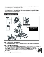
a. Attach the
Right Upright Post Sleeve (39)
on the
Upright Post (5)
and secure
with 2pcs
Bolts
(M5xp0.8x15mm)(87).
b. Attach the
Left Upright Post Sleeve (38)
on the
Upright Post (5)
and secure
with 2pcs
Bolts (M5xp0.8x15mm)(87)
and one
Screw (M4x20mm)(85).
S
TEP
5
–
Connection
Wire and Console Assembly
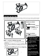
a. Plug the
Upper Connection Wire (112)
into the
Middle Connection Wire (113).
Be careful not to pinch the wires.
b. Plug the
Upper Pulse Sensor Wire (118)
into the
Middle Pulse Sensor Wire (119).
Be careful not to pinch the wires.
c. Place the
Console (31)
onto the
Upright Post (5)
and secure with 4pcs
Bolts (M5xp0.8x15mm)(87)
.
“
A
SSEMBLY
I
NSTRUCTIONS
”
S
TEP
6
–
Pulse Sensor Wire Assembly
a. Plug the
Middle Pulse Sensor Wire (119)
into the
Lower Pulse Sensor Wire (120).
Be careful not to pinch the wires.
S
TEP
7
–
Handlebar, Console Sleeve and Decoration Cover Assembly
NOTE:
For shipping purpose, 4pcs Bolts (M8xp1.25x16mm)(95) and 4pcs Lock Washers (M8)(74) are attached on the
Upright Post Assembly (5).
a. Remove 4pcs
Bolts (M8xp1.25x16mm)(95)
and 4pcs
Lock Washers (M8)(74)
from the
Upright Post Assembly (5)
.
b. Insert the
Handlebar (6)
into the
Upright Post Assembly (5)
and secure with 4pcs
Bolts (M8xp1.25x16mm)(95)
and
4pcs
Lock Washers (M8)(74)
.
c. Attach the
Console Sleeve (33)
to the
Console (31)
and secure with 4pcs
Bolts (M5xp0.8x15mm)(87)
.
d. Attach the
Upper Handlebar Decoration Cover (34)
and the
Lower Handlebar Decoration Cover (35)
to the
Summary of Contents for PR-8023
Page 29: ...27 PRODUCT PARTS DRAWING ...


