INSTALLATION
Installation
www.stiebel-eltron.com
LWE 40 |
31
EN
GL
ISH
f
f
To open the terminal, attach the tool and push it down.
Alternatively, you can open the terminal with a pointed
object from above or from the insertion side.
f
f
Insert a wire into the terminal.
D
00000
700
74
f
f
Push the plug-in connection into the retainer in the wall
mount casing.
f
f
Clamp the cable in a loop underneath the plug-in connection
between the plastic bosses.
5.2.1 Control unit and power supply unit
Material losses
Interchanging the connections may result in control unit
malfunctions.
Note
When using a differential pressure switch, always in-
terrupt the power supply to the control unit or power
supply unit.
Power supply unit for 2 appliances
D
00000
700
77
f
f
Install the power supply unit in the bottom half of the double
flush box.
f
f
Install the control unit in the top half of the flush box.
f
f
Connect the control unit to the power supply unit as per the
wiring diagram.
f
f
Observe the imprint on the control unit.
Power supply unit for more than 2 appliances
f
f
Connect a dedicated MCB upstream of the power supply unit
installed in the control panel.
The wiring from the control panel to the appliances is carried out
in a star pattern.
f
f
Install the control unit in the flush box.
f
f
Connect the control unit to the power supply unit as per the
wiring diagram.
f
f
Observe the imprint on the control unit.
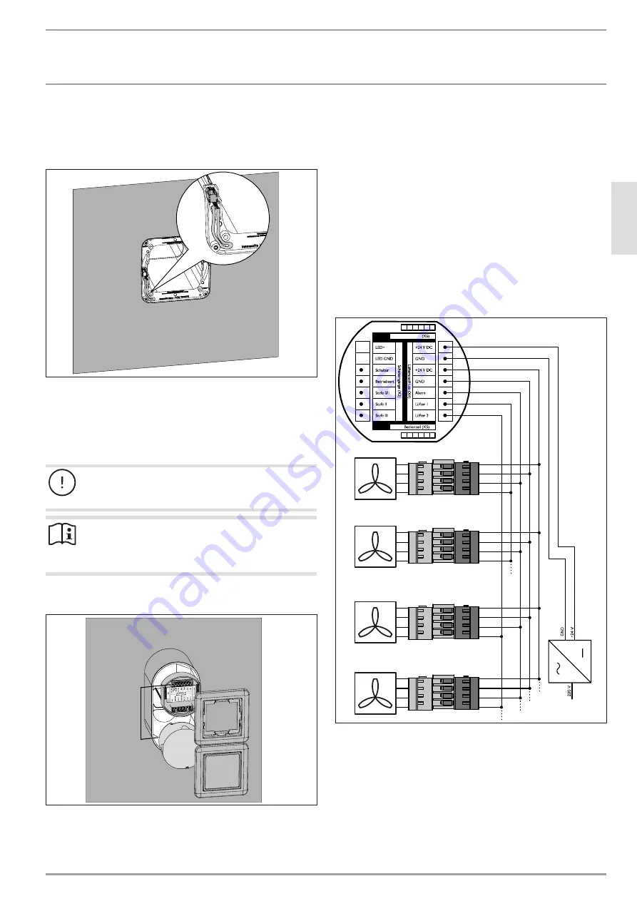
5.2.2 Wiring diagram with more than 2 appliances
1
2
3
4
1
2
3
4
1
2
3
4
1
2
3
4
D
00000
700
63
f
f
Assign the appliances in pairs to the "Fan 1" and "Fan 2"
terminals. Of the pair of appliances working in differential
mode, one must be connected to the "Fan 1" terminal and
the other to the "Fan 2" terminal. Check whether the pairs of
appliances are working in differential mode. In differential
mode, one appliance transports the extract air out of the
building to the outside. The other appliance draws outdoor
air into the building.


