OPERATION
Safety
EN
GL
ISH
www.stiebel-eltron-usa.com
SOL 29 Premium |
3
1.2
Other symbols in this documentation
NOTE :
Notes are bordered by horizontal lines above and below
the text. General information is identifi ed by the adjacent
symbol.
Read these texts carefully.
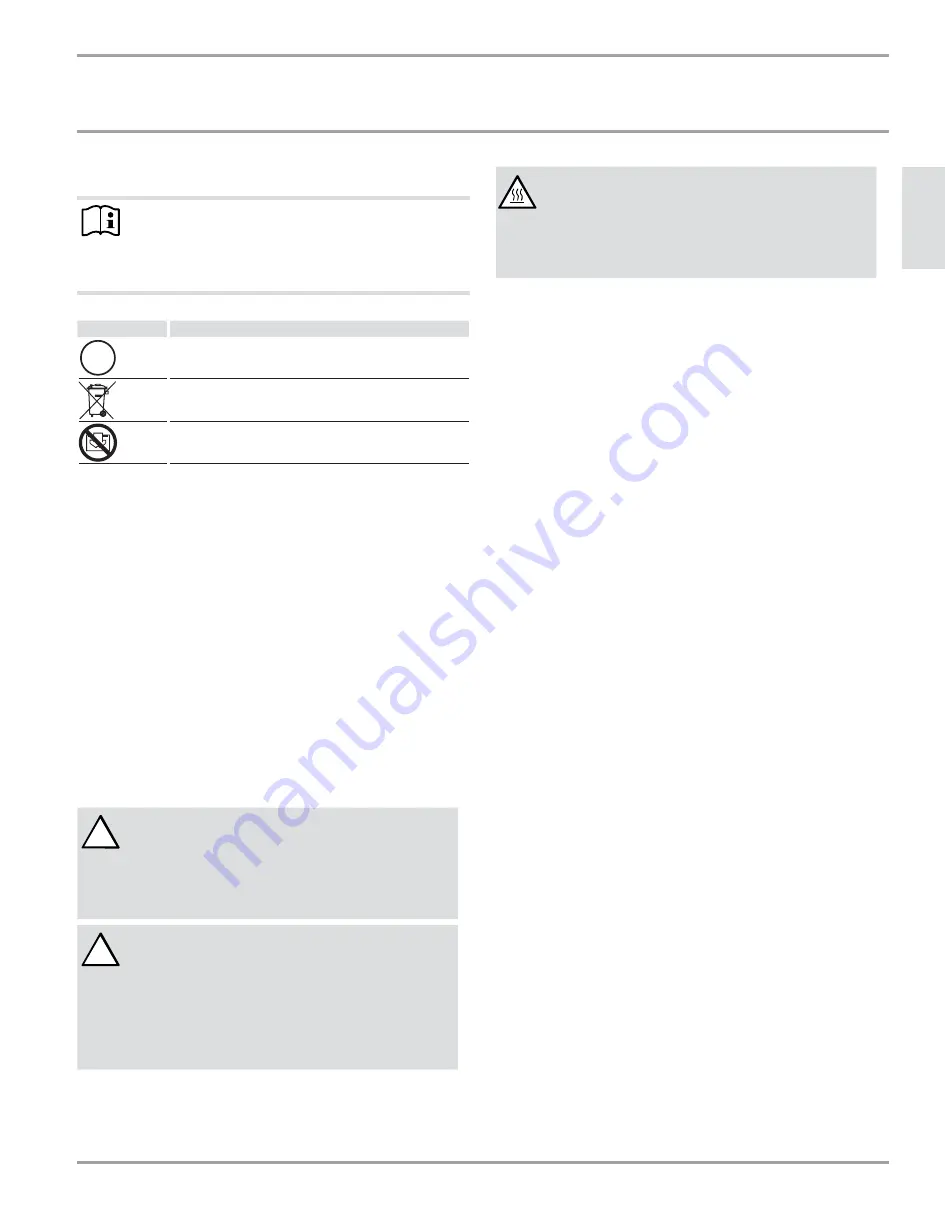
Symbol
Meaning
Material losses
(appliance damage, consequential losses and environmental
pollution)
Appliance disposal
Never cover the appliance
This symbol indicates that you have to do something. The ac-
tion you need to take is described step by step.
2.
Safety
Observe the following safety information and regulations.
Operate the appliance only when fully installed and with all safety
equipment fi tted.
2.1
Intended
use
This device is intended to produce hot water for domestic and hea-
ting use by collecting energy radiated from the sun.
Any other use beyond that described shall be deemed inappropriate.
Observation of these instructions and of instructions for any acces-
sories used is also part of the correct use of this appliance.
2.2 General
safety
!
WARNING:
A solar collector generates heat from sunlight. This
leads to the collectors and their connectors getting
very hot, even when they are not fi lled. Cover the col-
lectors with opaque material until the installation has
been completed.
!
WARNING:
Never install any valves or shut-off devices in the pip-
ing between the collectors and the safety valve. The
safety valve is activated at 87 psi.
Never set the solar loop pressure greater than the dhw
water supply pressure. If the potable water pressure is
too low, a booster pump may be needed to assure that
it exceeds the required solar loop pressure.
WARNING:
Scalding
Setting the maximum tank temperature higher than
140°F at the control unit is permissible only with a
thermostatically-controlled DHW mixing valve. Other-
wise there can be a risk of scalding at the tapping
point.
2.3 Mandatory
equipment
Check valve
Check valves must be installed on the supply and return piping to
the collectors to prevent heat loss via single-pipe thermosiphoning.
Drain valve
A drain valve must be installed at the lowest point of the solar ther-
mal system to aid in draining for maintenance.
Expansion tank
A diaphragm-type expansion tank must be installed to accept expan-
ding fl uid in the solar loop. The expansion tank should be designed
for an operating pressure of 87 psi and are resistant to deterioration
from propylene glycol mixtures.
The air-side inlet pressure should be set equak to the system start-
up (cold) pressure; check it when the system has not been fi lled or
when the wet side of the expansion tank is open to the atmosphere.
Solar heating fl uid
Use only a mixture of food-grade propylene glycol and de-ionized
water in the solar loop. The ratio of glycol to water should provide
suffi cient freeze protection below expected cold water temperatures
in the climate of the installation location.
Besides freezing, glycol must be used as a corrosion inhibitor in the
rest of the solar loop piping. See the specifi cations for the solar fl uid
in section 9.3 on page 13.
2.4 Emergency
shut-down
Except for repair and/or emergency, the control unit and the pump
must remain powered and activated in order to avoid overheating
the collectors. Prior to shutting down the system for repairs, cover
the solar collectors or work at night.
If emergency shut-down is needed, unplug the control unit and call
for service.
2.5 Licenses/certifi cates
- SRCC Standard 100-2006-09 (OG-100): 10002015
!


