background image

INSTALLATION 

Installation

8

 | SOL  29  Premium 

www.stiebel-eltron-usa.com

1

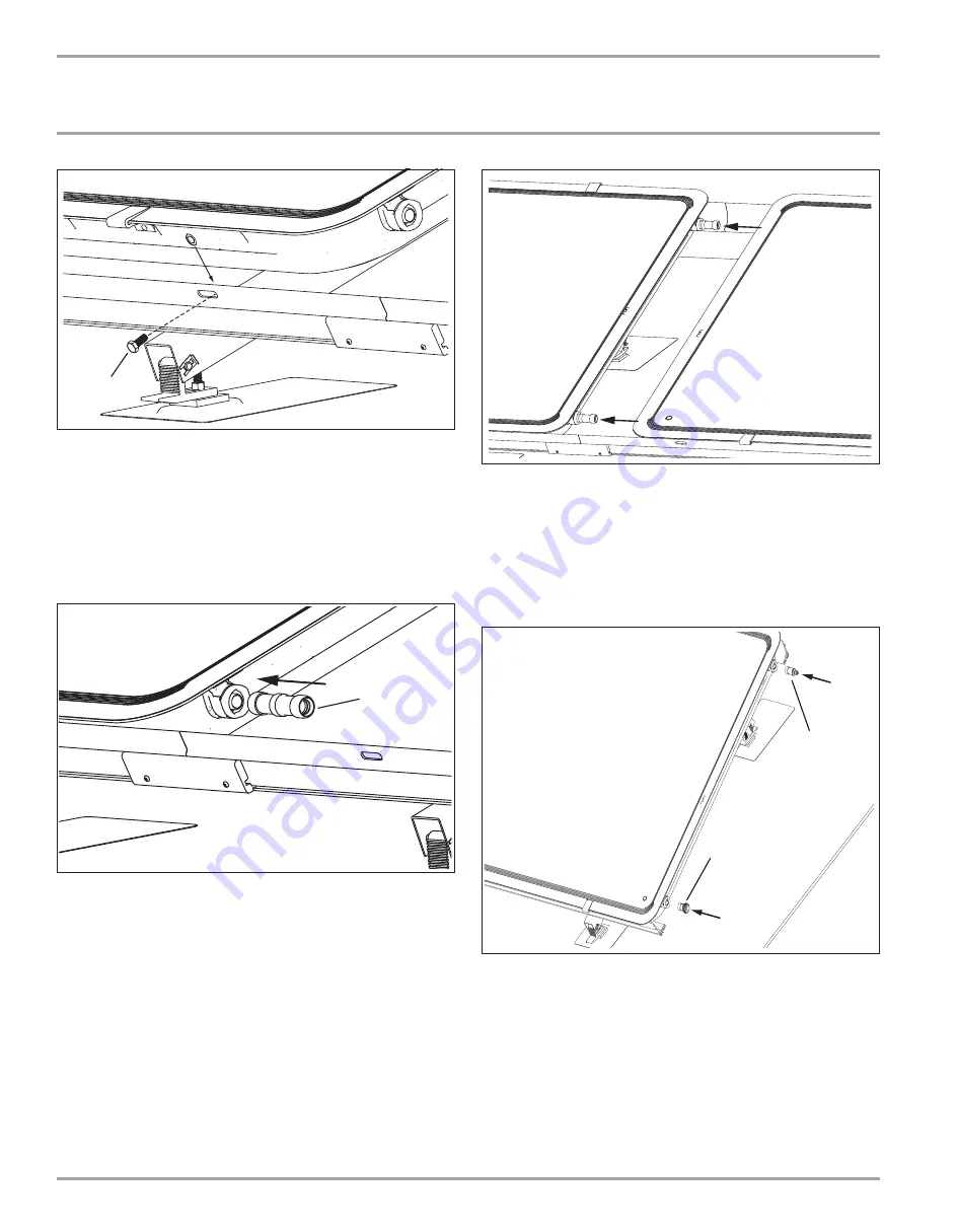
1  M8 x 20mm bolt

Place the collector into the collector frames and fasten the bolt th-
rough the collector frame into the collector. There are four fastening 
points on each collector that must be secured. Two bolts secure into 
the top of the collector, and two secure into the bottom.

6.8 Collector 

connection

6.8.1  Connection between collectors

1

1 Inter-panel connector

Push the inter-panel connectors completely into the collector 
connection. Do this for both connector ports on the side where the 
next collector will be installed.

Sit the next collector into the frames and slide the inter-panel 
connectors into the connections of the next collector.

Secure each collector with the M8 x 20mm bolts as each one is in-
stalled. Repeat the process with any additional collectors.

6.8.2  Connection at end of array

Cold inlet

1

2

1  Vent plug connector
2  1˝ male connector

On the connection side where the cold fl uid will enter the collector 
array, install a vent plug connector in the top collector connection 
and a threaded connector in the bottom collector connection.

Summary of Contents for 290016

Page 1: ...OPERATION AND INSTALLATION Solar Thermal Collector SOL 29 Premium S SOL 29 Premium W...

Page 2: ...__________________________________________ 3 2 4 Emergency shut down_____________________________________________ 3 2 5 Licenses certi cates________________________________________________ 3 3 Registe...

Page 3: ...WARNING Scalding Setting the maximum tank temperature higher than 140 F at the control unit is permissible only with a thermostatically controlled DHW mixing valve Other wise there can be a risk of s...

Page 4: ...installation of solar thermal collectors typically involves installa tion on a roof or otherwise elevated structure Refer to all relevant safety codes to ensure that installation can be completed with...

Page 5: ...e table below for the rafters that will need to be secured to This is a minimum speci cation It may be possible or necessary to add more mounting racks per array if needed to spread out the roof load...

Page 6: ...section 6 4 1 on page 5 Uproof 2 1 1 Mounting point spacing between rafters 2 Front and back mounting spacing Repeat the mounting process for all ashing kits in the array Pay attention to vertical var...

Page 7: ...ear one of the four con nection points This sensor well must be oriented so that a sensor can measure the temperature of the solar uid as it exits the array Do not orient the collector so that the sen...

Page 8: ...nectors completely into the collector connection Do this for both connector ports on the side where the next collector will be installed Sit the next collector into the frames and slide the inter pane...

Page 9: ...the hot uid exits the collector array install a threaded connector in the top collector connection and a plug connector in the bottom collector connection WARNING Burns Once the collectors are install...

Page 10: ...ave been connected it will be necessary to pressure test the system to detect leaks before lling the solar loop with heat transfer uid Propylene glycol solutions can leak from much smaller gaps than c...

Page 11: ...tions on how to ll ush charge the solar loop consult the pump station manual 8 Maintenance care Specialists should carry out an annual inspection of the solar he ating system to ensure proper function...

Page 12: ...s Glass thickness 1 8 3 mm Glass transmittance 89 Thermal insulation 2 50 8 mm mineral wool Collector connection 1 BSPP thread ships with adapters Max idle temperature 345 F 174 C Min operating pressu...

Page 13: ...pylene Glycol 94 Weight performance additives 6 Specific gravity 60 F 15 C 1 053 1 062 pH of Solution 9 5 10 5 Reserve alkalinity 15 0 ml Vapor pressure over operating range 2 2 mmHg Flash point 219 F...

Page 14: ...Collectors Collectors number type Collector surface area System speci cations System height Pipe run length Ventilation Solar uid type concentration Max ow rate Pump station Pump setting low med high...

Page 15: ...7 to propylene glycol ph levels above 10 or below 8 8 to periods of stagnation in excess of 60 days 9 to excessive pressure 10 to clouding or similar occurrence resulting from the normal intrusion of...

Page 16: ...chnological advancement speci cations may change without notice Stand 8643 STIEBEL ELTRON Inc 17 West Street West Hat eld MA Tel 0413 247 3380 Fax 0413 247 3369 info stiebel eltron usa com www stiebel...

Reviews: