iNSTallaTiON
Commissioning
EN
GL
ISH
www.stiebel-eltron.com
DCE-S Plus |
9
10. Commissioning
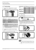
10.1 Internal anti-scalding protection via jumper
slot
43 °C | 109 °F
50 °C | 122 °F
55 °C | 131 °F
60 °C | 140 °F
D
00000
73
62
4
f
Install the jumper in the required position on the "Tmax" pin
strip.
Jumper position
Description
43 °C | 109 °F
For example in nurseries, hospitals, etc.
50 °C | 122 °F
55 °C | 131 °F
Max. for shower operation
60 °C | 140 °F
Factory setting
No jumper
Limit 43 °C | 109 °F
CAUTION Burns
If operating with preheated water, e.g. if using a solar
thermal system, the internal anti-scalding protection can
be overridden.
f
In this case, limit the temperature with an upstream
central thermostatic valve.
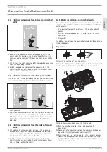
10.2 Changing the connected load via the jumper
slot
If you select a connected load other than the factory setting for
the appliance, you will need to reposition the jumper.
1
2
D
00000
82
93
8
f
Install the jumper in the required position on the "Pmax" pin
strip.
Jumper position
Connected load
DCE-S 6/8 Plus DCE-S 10/12 Plus
1 [low]
@ 220 V
6.0 kW
10.0 kW
@ 230 V
6.6 kW
11.0 kW
@ 240 V
7.2 kW
12.0 kW
2 [high]
@ 220 V
8.0 kW
12.0 kW
Factory setting
@ 230 V
8.7 kW
13.1 kW
@ 240 V
9.6 kW
14.3 kW
No jumper [low]
@ 220 V
6.0 kW
10.0 kW
@ 230 V
6.6 kW
11.0 kW
@ 240 V
7.2 kW
12.0 kW
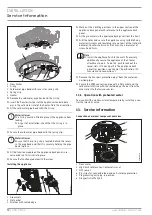
10.3 Initial start-up
f
Tick the selected connected load on the type plate. Use a
ballpoint pen to do this.
≥ 3 min.
on
15 x
off
D
0000
10
15
20
f
Open and close all connected draw-off valves 15 times
over a period of at least 3 minutes, until all air has been
purged from the pipework and the appliance. Vent the cold
water inlet line and the appliance using a flow rate of least
3.5 l/min.
f
Carry out a tightness check.
D
00000
73
62
2
f
Activate the safety switch by firmly pressing the reset button
(the appliance is delivered with the safety switch disabled).
D
00000
82
93
7
f
Insert the plug of the programming unit connecting cable at
the PCB.
Note
It is essential to plug the connecting cable for the pro-
gramming unit into the PCB before switching on the
power. Otherwise, the programming unit will not func-
tion.
Summary of Contents for DCE-S 10/12 Plus
Page 67: ...www stiebel eltron com DCE S Plus 67 3 70 C 43 C 55 C 55 C 3 mm...
Page 68: ...68 DCE S Plus www stiebel eltron com 1 1 1 1 1 1 f 1 1 2 1 1 3 1 2 f f 1 3 2 2 1...
Page 69: ...www stiebel eltron com DCE S Plus 69 2 2 70 C 43 C f 3 IP 25 2 3 3 f f f...
Page 79: ...www stiebel eltron com DCE S Plus 79 14 LED LED 1 1...
Page 85: ...www stiebel eltron com DCE S Plus 85 3 70 C 43 C 55 C 55 C 3...
Page 86: ...86 DCE S Plus www stiebel eltron com 1 1 1 1 1 1 f 1 1 2 1 1 3 1 2 f f 1 3 2 2 1 2 2 70 C 43 C...
Page 97: ...www stiebel eltron com DCE S Plus 97 14 LED 1 1...
Page 103: ...www stiebel eltron com DCE S Plus 103...
Page 104: ...DCE S Plus www stiebel eltron com...
Page 108: ...3 DCE S Plus www stiebel eltron com 4 LED LED 5...
Page 110: ...DCE S Plus www stiebel eltron com D 4 5 D 3 4 2 45 44 46 D 3 45 1 4 5 2 3 D...
Page 111: ...www stiebel eltron com DCE S Plus D 3 42 D 532 D 4 D 3 2 2 2...
Page 113: ...www stiebel eltron com DCE S Plus D 4 3 2 5 2 3 45 4 5 D 545 5 4 5 D 3 44 3...
Page 115: ...www stiebel eltron com DCE S Plus 55 IP 25 4 5 45 2 2 2 UP Kit EU 2 45 D 3 2 2 2 D 3 2...
Page 116: ...5 DCE S Plus www stiebel eltron com 5 3 55 55 4 5 Nr 000000 0000 00000 D 3 2...
Page 117: ...www stiebel eltron com DCE S Plus 4 43 3 IP 25 3 D 2 2...
Page 118: ...3 DCE S Plus www stiebel eltron com 3 43 55 55 3...


