INsTALLATIoN
Specification
50
| ETW 120-480 Plus
www.stiebel-eltron.com
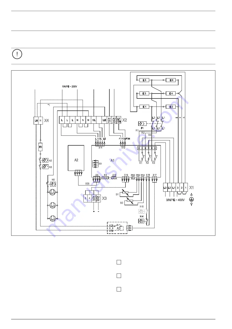
19.2 Wiring diagram
Material losses
Ensure that the differential in potential between connections L, L1 on the mains power side and the various control signals SL,
A1, A2, LF, SH, LE and LH does not exceed 230 V.
1/N/PE ~ 230V
M2
M3
M1
N5
A1
X 9
N
L
LE
SL
X 11
A1A2LF/SH
X 12
A3
L3 L2 L1
K3
K1
R1
R3
R2
K2
ws br vi
E 5
E 3
E 1
E 2
E 6
E 4
F1
L3 L2 L1
X 9
X 9
X 13
X 15
X 18 X 17
X10.3 X10.2 X10.1
N 4
N 6
L
N
LE A1
Z1
SL
N
N
L
L
LF
SH
A2
Z2
X2
B2
B1
L2
L3
L1
2
3
X1
1
A2
4
X3
3
A1
Z1
A2
Z2
-
+
N2
N3
E8
X4
*1
LH N
X25
3/N/PE ~ 400V
D
00000
75
34
5
Booster heater
Control
external (LH)
DC
Charge control system
LV system
AC
Charge control system
230 V system
Fan
Control
external (LE)
Storage component
A1
Electronic charge/discharge controller
A2
User interface PCB
B1
Core sensor – charge
B2
Room temperature sensor – discharge
F1
High limit safety cut-out
E1 - E6 Heating element
M1 - M3 Storage heater fan
N4
Temperature limiter – charge
N5
Protective temperature controller
N6
Temperature limiter – charging level
only for 3.0 - 4.8 kW
X25
Internal connecting lead A1 - A2
X1
Mains terminal
X2 Terminal
Accessories
(Not part of the standard delivery. Tick the boxes to show the
accessories installed.)
DC connection
X3 Terminal (0.91 - 1.43 V)
Booster heater
(internally controlled)
*1 / wire LH - L
Booster heater
(externally controlled)
A3 Booster heater assembly relay
E8 Booster heater element
N2 Temperature controller - booster heater
N3 Temperature controller - booster heater
X4 Terminal


