background image

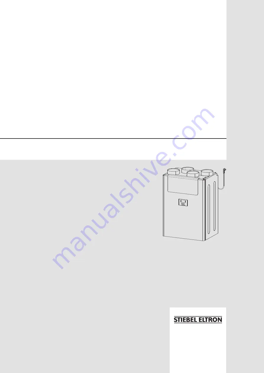
BEDIENUNG UND INSTALLATION
OPERATION AND INSTALLATION
USO E INSTALLAZIONE

Zentrales Lüftungsgerät mit Wärmerückgewinnung | Central ventilation appliance 
with heat recovery | Apparecchio di ventilazione centralizzata con recupero di 
calore


» LWZ 180


» LWZ 280


» LWZ 180 Enthalpie


» LWZ 280 Enthalpie

Summary of Contents for LWZ 180 Enthalpie

Page 1: ...NSTALLATION USO E INSTALLAZIONE Zentrales Lüftungsgerät mit Wärmerückgewinnung Central ventilation appliance with heat recovery Apparecchio di ventilazione centralizzata con recupero di calore LWZ 180 LWZ 280 LWZ 180 Enthalpie LWZ 280 Enthalpie ...

Page 2: ... Installation location 34 9 3 Transport 34 10 Installation 35 10 1 Removing the front panel 35 10 2 Mounting the appliance 35 10 3 Connecting the condensate drain hose 35 10 4 Air ducts 36 10 5 Fitting the front panel 37 10 6 Electrical connection 37 11 Commissioning 38 11 1 Initial start up 38 11 2 Recommissioning 38 12 Settings 39 12 1 Parameters 39 12 2 Actual values 40 12 3 Code 40 13 Applianc...

Page 3: ... you have to do something The ac tion you need to take is described step by step 1 3 Information on the appliance Connections Symbol Meaning Outdoor air Exhaust air Extract air Supply air 1 4 Standardised output data Explanations to determine and interpret the specified standardised output data Standard EN 13141 7 EN 12102 The output data specifically mentioned in text diagrams and technical datas...

Page 4: ...tage Display Ventilation for humidity protection 0 Power symbol and digit 0 Necessary ventilation for ensuring that the building structure is protected under normal conditions of use with somewhat reduced moisture loads e g during tem porary absence of users and no drying of washing in the residential unit Reduced ventilation 1 Fan sym bol and digit 1 Reduced ventilation is the ventilation necessa...

Page 5: ...and OK buttons simultaneously for two seconds to deactivate the function block 4 2 2 Display If no user action occurs within the time selected in the illumination duration parameter the display backlighting switches off and the standard display appears Press any button to switch the backlighting on again Symbol Description Power This symbol indicates that the appliance is switched on and the fans ...

Page 6: ...he heat exchanger 2 The bypass operates with summer day detection This option is set in the delivered condition 3 The bypass operates subject to the extract air temperature Note The qualified contractor can set the parameters men tioned in the description of this parameter P23 Frost protection mode P24 Bypass enable temperature P25 Bypass blocking temperature P26 Bypass hysteresis P27 Temperature ...

Page 7: ... x 3 x 4 Day or group of days Fan stage Start time Stop time 16 17 18 19 20 21 Setting a time program begins with selecting a day of the week or a group of days Press the OK button Set the day using the Touch Wheel Confirm with the OK button Use the Touch Wheel to switch to setting the fan stage Press the OK button Set the fan stage in which the appliance runs when the time program takes effect us...

Page 8: ...ecessary place one or more new filters in the filter drawer Ensure that the filters are installed in the intended position Air flows through the filters from top to bottom The flow direction is indicated with an arrow on the filter drawer fascia The outdoor air filter is marked with an arrow Install the outdoor air filter with the arrow pointing in the flow direction The extract air filter is impr...

Page 9: ...alled The combustion equipment must also have a separate combustion air supply With open flue combustion equipment a differentiation must be made between alternate and simultaneous operation of the ven tilation system and combustion equipment Alternate operation Alternate operation means that when the combustion equipment is started the mechanical ventilation system is switched off and or cannot b...

Page 10: ...he wall on which the appliance is to be mounted has sufficient load bearing capacity A plaster board or metal framed wall is inadequate Additional measures such as a double skin or additional supports would be needed in such cases Ensure the appliance is level after installation The installation room must have an adequate condensate drain with siphon The installation room must be free from the ris...

Page 11: ...he rail f f Remove the wall mounting bracket from the appliance D0000040851 f f Secure the wall mounting bracket to the wall with four screws The text TOP must be at the top The wall mounting bracket must be horizontal f f If necessary screw the star grips included in the standard delivery into the back of the appliance at the bottom to act as spacers f f Fit the appliance onto the hooks of the wa...

Page 12: ...the ventilation system Material losses During installation ensure that no metal swarf enters the pipework However should this occur remove this debris otherwise the fans may be damaged Install the air ducts using materials that can be obtained from us or with commercially available folded spiral seam tubes 10 4 1 Connecting air ducts to the appliance You can connect air ducts with two different di...

Page 13: ...Install ventilation grilles in internal doors or walls or enlarge the air gap beneath the door to 8 mm 10 4 5 Cleaning apertures f f Fit cleaning apertures when installing the air ducts so that the air ducts can be inspected and cleaned at regular intervals 10 4 6 Supply and extract air vents Supply and extract air vents for the living space are available for wall or ceiling mounting When venting ...

Page 14: ...itches the appliance to intensive ventilation You can set the runtime for intensive ventilation in parameter P2 After this time has expired the appliance returns to the previously appli cable fan stage f f Connect the external switches to terminals 13 14 External programming unit The programming unit is connected with an I C bus 11 Commissioning Material losses Never operate the appliance without ...

Page 15: ...e maintains a constant flow rate for both fans The appliance operates with set flow rates P6 to P9 1 The appliance maintains a constant pressure at the extract air fan The appliance regulates the pressure at the extract air connector to the set values saved in P10 to P13 The flow rate that is established there is used as the set value for flow rate control of the supply air fan The supply air flow...

Page 16: ...lated supply air flow rate m h I17 Exhaust air fan drive output I18 Calculated exhaust air flow rate m h I19 Percentage output of internal preheater I20 Ventilation unit operating time d I21 Fan operating time d I22 Extract air pressure differential Pa I70 79 Fault 12 3 Code Cod Enter 1000 to enable actual values and parameters which are re served for qualified contractors A1 is shown on the displ...

Page 17: ...back Release the eccen tric bolt before pulling out the fan unit Retighten the eccentric bolt after installing the fan unit 300 D0000063652 1 2 1 Eccentric bolt tightened slot horizontal 2 Eccentric bolt released f f Use a medium sized screwdriver to turn the eccentric bolt anti clockwise by 300 f f Carefully pull both fan units from the appliance by a small amount D0000040366 4 3 1 2 1 Temperatur...

Page 18: ...rs must face down f f Hook the fascia into the appliance Cleaning the air ducts Air ducts must be checked at regular intervals and cleaned if nec essary Disconnect the air ducts from the appliance or carry out in spection and cleaning through the extract air and supply air vents 15 Troubleshooting WARNING Electrocution Disconnect the power supply by unplugging the appli ance from the mains before ...

Page 19: ... Supply air Diameter mm 160 180 160 180 160 180 160 180 i13 Wall mounting bracket 16 2 Wiring diagram X1 Power supply X2 Heating coil X3 Supply air fan power cable X4 Exhaust air fan power cable X6 Float switch X7 Supply air temperature sensor X8 Exhaust air temperature sensor X11 I C bus at terminal block X12 Internal programming unit X13 External programming unit X15 Outdoor air humidity sensor ...

Page 20: ... Specification X3 X22 X7 X23 X24 X4 X21 X5 X6 X8 X9 X10 X16 X15 1500 W E1 F1 M X17 X12 X14 X11 X18 X19 X20 X13 X2 X1 L N PE bn bl bl bn Heizregister Bypass Schwimmer AUL ABL ZUL FOL 1 1 1 int Bedienteil 1 1 1 1 1 1 1 1 1 1 1 1 1 9 1 1 1 1 1 1 1 D0000065014 ...

Page 21: ...8 0 34 0 29 0 20 0 16 0 06 0 03 0 09 0 03 0 05 0 40 0 17 D0000063739 X Air flow rate m h Y Average value static pressure Pa z Power consumption of both fans Wh m Application range LWZ 280 LWZ 280 Enthalpie 0 25 50 75 100 125 150 175 200 225 0 25 50 75 100 125 150 175 200 225 250 275 300 325 350 0 49 0 26 0 30 0 42 0 17 0 10 0 16 0 20 0 04 0 11 0 24 0 36 0 32 0 24 0 19 0 06 0 02 0 12 0 04 0 08 0 40...

Page 22: ...wer consumption W 65 130 65 130 Power consumption without preheating coil W 65 130 65 130 Power consumption with preheating coil W 1565 1630 1565 1630 Versions IP rating IP21 IP21 IP21 IP21 Filter class M5 G4 F7 optional M5 G4 F7 optional M5 G4 F7 optional M5 G4 F7 optional Dimensions Height mm 997 997 997 997 Width mm 690 690 690 690 Depth mm 534 534 534 534 Weights Weight kg 78 78 80 80 Connecti...

Page 23: ...ued by those subsidiaries Such guarantee is only grant ed if the subsidiary has issued its own terms of guarantee No other guarantee will be granted We shall not provide any guarantee for appliances acquired in countries where we have no subsidiary to sell our products This will not affect warranties issued by any importers Environment and recycling We would ask you to help protect the environment...

Page 24: ...tron cz www stiebel eltron cz Finland STIEBEL ELTRON OY Kapinakuja 1 04600 Mäntsälä Tel 020 720 9988 info stiebel eltron fi www stiebel eltron fi France STIEBEL ELTRON SAS 7 9 rue des Selliers B P 85107 57073 Metz Cédex 3 Tel 0387 7438 88 Fax 0387 7468 26 info stiebel eltron fr www stiebel eltron fr Hungary STIEBEL ELTRON Kft Gyár u 2 2040 Budaörs Tel 01 250 6055 Fax 01 368 8097 info stiebel eltro...

Reviews: