5
Installation instructions
for the installer
Regulations and provisions
– General national regulations
– Regulations of the local water
authority
– Regulations of the local electricity
authority
– Rating plate
Installation location
– Install vertical as in Fig.
– In an area free of the risk of freezing
– Install in the vicinity of the water tap
Equipment installation
– Install the device
When installing the device, select securing
materials to suit the stability of the wall
Temperature adjustment Fig.
PSH 30 Si / PSH 50 Si
The temperature adjustment for the PSH 30
Si and PSH 50 Si may be altered by the user
directly at the temperature knob.
For PSH 80-150 Si see Fig. .
Water connection Fig.
Unvented (pressurized) for the supply of
several draw-off points.
A safety valve must be fitted with on
the cold water inlet of the unit, by a
skilled installer.
2. Installation instructions
for the qualified installer
Legend for Fig.
1
PSH wall-mounted water heater
3
Safety valve, 6 bar
4
Pressure Limiting valve
(recommended for pressures
over 5 bar)
5
Back-flow prevention device
6
Through-flow isolating valve
(throttle)
7
Cold water pipe
8
Drainage tap
9
Connection for isolating element
made of red brass or plastic, for
cold and hot water
10 Hot water pipe
11 Draw-off fittings
– Permissible operating
overpressure 6 bar.
– Install only type-tested safety
valves or safety groups.
Specific national regulations
are to be respected.
– Arrange the dimensions of the
drain to suit the fully-opened
safety valve. The drain aperture of
the safety valve must remain open
to the atmosphere.
– Adjust through-flow volume
max. 18 l/min at the through-flow
isolating valve (Fig.
-6).
– During the heating-up process,
water will visibly drip from the
safety valve.
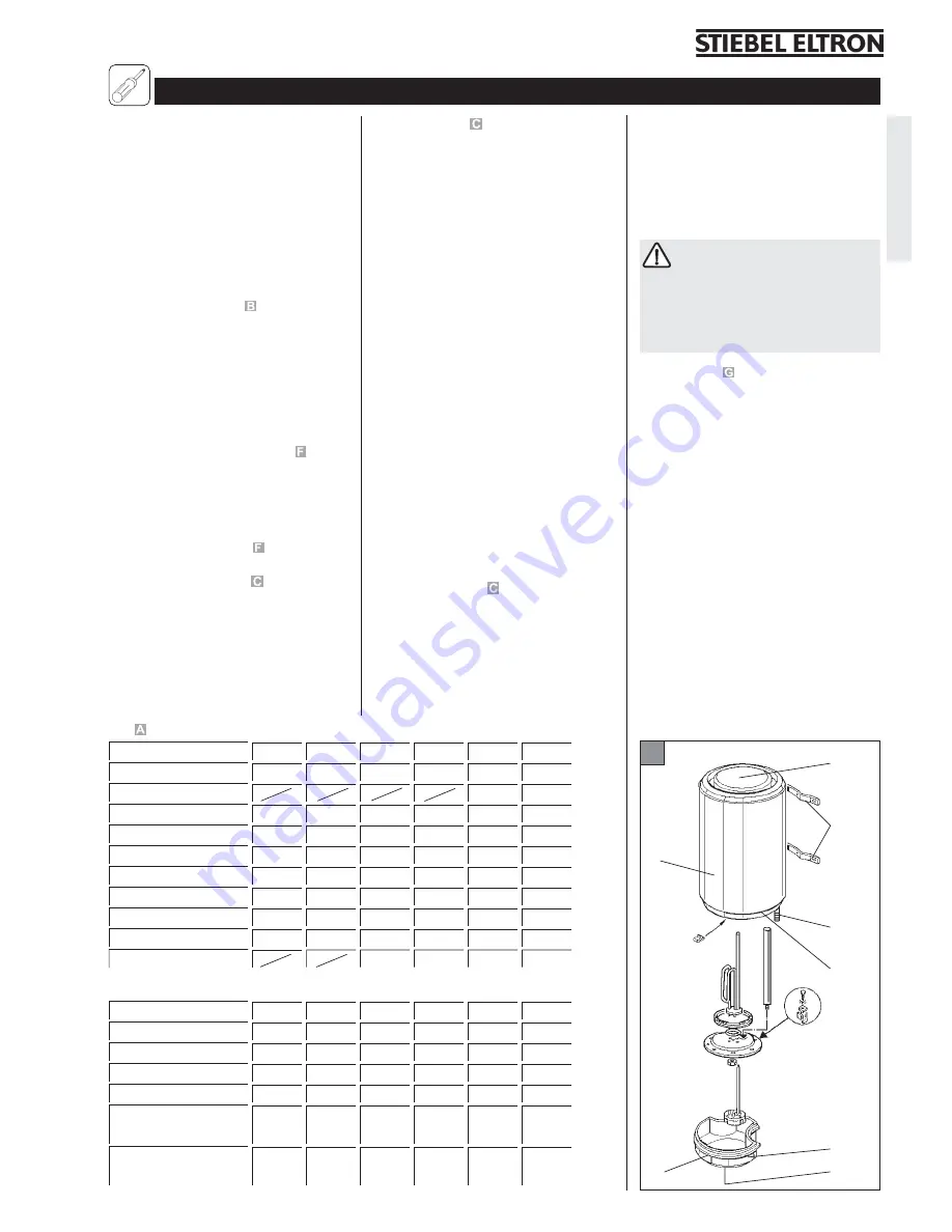
Parts Fig.
1 Plastic top cap
2 Wall brackets
(on PSH 30 - 100 Si, on top only)
3 Sheet steel housing, white
paint finish
4 Cold water connection nozzle (blue)
5 Hot water connection nozzle (red)
6 Plastic bottom cap
7 Electric housing with electrical
connection
8 Temperature knob (only PSH 30-50 Si)
9 Lamp
Steel tank enamelled with heating flange with
copper tubular heating element and
protection anode.
For test mark: see rating plate
Protection mode IP 25
G
– If water continues to drip from the
safety valve after the heating
system has been switched off, the
water pressure is too high (>6 bar),
or the safety valve has been
contaminated with dirt or is
defective.
Note with regard to copper pipes:
No connections made of copper
may be installed directly on the
device. We recommend that red
brass or plastic transition fittings be
used as connection isolators for the
pipe connections.
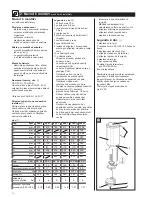
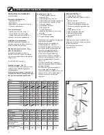
Type
PSH
30 Si
50 Si
80 Si
100 Si
120 Si
150 Si
Content
30
50
80
100
120
150
Weight, emty
kg
14
17
26
31
34
40
Power rating
W
2000
2000
2200
2200
2200
2200
Voltage
V
230
230
230
230
230
230
Permissible operating
pressure
bar
6
6
6
6
6
6
Standby current
consumption at
65 °C/24h
kW/h
0,73
0,99
0,97
1,21
1,3
1,46
Typ
PSH
30 Si
50 Si
80 Si
100 Si
120 Si
150 Si
A
mm
623
918
780
911
1046
1256
B
mm
498
798
C
mm
345
368
570
748
748
1048
D
mm
160
168
230
230
230
230
E
1/2"
1/2"
3/4"
3/4"
3/4"
3/4"
F
mm
100
100
230
230
230
230
G
mm
81
81
170
170
170
170
H
mm
338
338
505
505
505
505
J
mm
345
345
520
520
520
520
K
mm
440
440
440
440
Fig.
1
2
3
4, 5
6
7
8
9
English
Summary of Contents for PSH 150 Si
Page 18: ...18 2 1 2 3 4 5 6 1 2 3 4 PSH 80 150 Si 5 65 C 3...
Page 24: ...24 2 3 1 2 3 4 5 6 1 2 3 4 F PSH 80 150SI 5 65 C 1...
Page 28: ...28 Notizen...
Page 29: ...29 Notizen...


