6
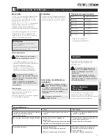
2. Installation instructions
for the qualified installer
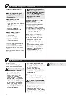
Electrical connection
Electrical connection may only
be carried out by a qualified
installer, in accordance with these
instructions.
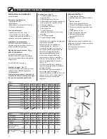
Legend, Fig.
1 Mains connection
2 Protective earth connection
3 Safety thermal cut-out Thermo-
stat combination
4 Plug connection-tubular heating
element
5 Lamp "Heating"
6 Temperature knob
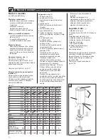
Legend, Fig.
1 Mains connection
2 Protective earth connection
3 Safety thermal cut-out Thermo-
stat combination
4 Plug connection-tubular heating
element
The device is intended for fixed connection
to
AC
mains supplies using permanently-laid
connection leads.
Specific national regulations are to be
respected.
First fill the device completely
with water, then connect the
current supply. The device may not
be taken into operation without water
filling (see also First start-up).
Temperature adjustment Fig.
PSH 80 -150 Si
The temperature adjustment set at the
works may be altered by a qualified installer.
To do this, the thermostat fitted inside the
device has to be turned to the appropriate
position: “
–
”:
Pos. 5 approx. 65 °C
First start-up
Only to be carried out by a qualified
installer, in accordance with these
instructions.
– Before switching on, fill the device
by opening the hot water valve and
flush it through thoroughly.
– Monitor first heating; check to
ensure that the thermostat
switches off.
– Check the safety valve or safety
group for functional reliability.
3. Maintenance
for the qualified installer
Maintenance
Only to be carried out by a qualified
installer, in accordance with these
instructions.
When carrying out any work,
disconnect the device from the
electricity supply!
– Check the protective anode for the first
time after one year, and replace it if
necessary; see “Spare parts” for order
number. After replacement, the installer
has to decide when next inspection is
necessary.
– Carry out descaling of the device only
after removing the heating element. Do
not treat the surfaceof the tank with
descaling agents.
– In the event of the thermal cut-out
having operated (no through-flow),
replace the regulator/limiter combination.
– Check the safety valve or safety group
regularly acc. to manufactores
specification.
Draining the cylinder
Draining can only be carried out via
the safety valve or through the additionally
fitted drainage tap.
Before draining the device, disconnect
the device from the electricity supply!
– Close the isolating valve in the
cold water pipe.
– Open all hot water valves fully at
all draw-off points.
– Open safety valve or drain valve.
Hot water may emerge during
draining.
Summary of Contents for PSH 150 Si
Page 18: ...18 2 1 2 3 4 5 6 1 2 3 4 PSH 80 150 Si 5 65 C 3...
Page 24: ...24 2 3 1 2 3 4 5 6 1 2 3 4 F PSH 80 150SI 5 65 C 1...
Page 28: ...28 Notizen...
Page 29: ...29 Notizen...


