background image

qqqĪZ`.<é<`VHCĪHB

ZH<ŝŌTVB.eB’ōŌ

IT

ALIANO

.CZ`<<x.HC

BZZ.C%eCx.HC

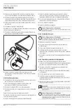
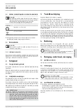
10.16 Isolamento termico

Assicurarsi di sottoporre l'impianto prima di montare la 
coibentazione ad una prova di pressione e un controllo della 
tenuta.

Coibentare tutte le tubazioni. Il materiale da utilizzare per la 
coibentazione deve essere affrontato in loco.

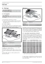
ê|ă¼ŒļĒêĉŒ¼ļĉĒŒşê
•ăă–

ZĤ¼ńńĒļ¼®¼ùùĻêńĒù|ă¼ĉŒĒŒ¼ļăê›Ē
ĦļêϼļêŒĒ|şĉŶ|ùĒļ¼®ê›Ēĉ®ş›êêùꌅ
Œ¼ļăê›|®êƃ©ƃŗÑqŎĦă:ħ|Ôƃ³ħ

fino a 22

20

22 - 35

30

35 - 100

Uguale al diametro interno del tubo

Se si utilizzano materiali isolanti con altri valori di conducibilità 
termica, calcolare gli spessori dello strato isolante. 

Per il rivestimento termico delle tubazioni esterne impiegare 
materiale isolante resistente a temperatura e ai raggi UVA: Lana 
minerale, rivestita con maglia di alluminio, tubo flessibile in EPDM 
o un tubo poroso chiuso EPDM.

Per la lana minerale si consiglia un solido rivestimento in lamiera 
di alluminio. Il tubo flessibile in EPDM può essere provvisto di una 
protezione resistente ai raggi UVA.


f

La sonda a immersione del collettore, i raccordi a vite e la 
canalina passante nel tetto devono essere provvisti di un 
isolante completamente stagno e resistente a temperatura e 
ai raggi UVA.


f

Tagliare eventualmente materiale isolante sul lato e chiudere 
con colla il taglio dopo il montaggio.


f

Proteggere il rivestimento termico da morsi di roditori e 
beccate di volatili.

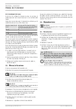
11.  Messa in funzione 


f

Serrare nuovamente tutti raccordi a vite. 


f

Verificare la pressione di riempimento dell'impianto.


Avvertenza
La pressione di riempimento minima a impianto freddo 
(sotto i 30 °C) deve essere 0,35 MPa (3,5 bar).


f

Verificare la pressione iniziale del serbatoio per la 
compensazione della pressione.


Avvertenza

Il serbatoio per la compensazione della pressione deve 
avere una pressione iniziale 0,3 MPa (3 bar).


f

Combinare il “registro messa in funzione chiuse le virgolette.


f

Impostare il regolatore integrato sull'esercizio manuale. 
Osservare le istruzioni per l'installazione e l'uso della 
regolatore integrato negli impianti.


f

Verificare che tutti i relè necessari della regolatore solare 
siano allacciati.


f

Reimpostare il regolatore sull'esercizio automatico.

Quando le condizioni di attivazione sono soddisfatte l'impianto 
dovrebbe rientrare automaticamente in esercizio. In caso 
contrario, ricercare la possibile causa del malfunzionamento nel 
capitolo “Cosa fare se ...”  

12. Manutenzione


Avvertenza

Vi offriamo l‘opportunità di stipulare un contratto di 
manutenzione.

12.1 Manutenzione


f

Verificare il funzionamento ineccepibile dell'impianto inclusi 
il regolatore, dispositivi di sicurezza e accumulatore.


f

Verificare che i componenti di un impianto esposti agli agenti 
atmosferici, i fissaggi e la coibentazione siano in perfette 
condizioni.


f

Eliminare la sporcizia.


f

Verificare il valore di pH (>7) del liquido termo vettore e 
sicurezza antigelo (-- 30 °C). Sostituire il liquido termo vettore 
oppure per rabboccare dalle bocche di riempimento della 
stazione sola.

!


CAUTELA Ferita
Nel caso sia necessario nel corso degli interventi di 
riparazione o manutenzione lo scaricamento di liquido 
termo vettore, è necessario che quest‘operazione sia 
eseguita da un tecnico specializzato..


Danni all‘apparecchio e all‘ambiente

Brilla di rimuovere il liquido termo vettore dal collettore, 
il collettore deve essere protetto dall‘incidenza della luce. 
Coprire il collettore in modo che non passi la luce.

Summary of Contents for SOL 27 PREMIUM S

Page 1: ...CeC eC CZ HC HT V HC C CZ HC e Z HC CZ HC eZH CZ x HC C C C CZ H Z eC Z H HV T V HVB C T H HV T eV T e T V HVB C H HV T H H V C B C H T H HV B HH V C B C ZH TV B eB Z ZH TV B eB q...

Page 2: ...________4 INSTALLATION 7 Sicherheit _____________________________________________________5 7 1 Vorschriften Normen und Bestimmungen_________________ 5 7 2 Sicherheitshinweise__________________________...

Page 3: ...rentem Einscheibensicherheitsglas Das Licht trifft auf den Absorber und wird dort in W rme um gewandelt Durch die hochselektive Beschichtung des Absorbers und die W rmed mmung auf der Absorberr ckseit...

Page 4: ...vermeintlich sp t an und schaltet fr h ab Wenden Sie sich an einen Fachhandwerker Die Pumpe l uft an und schaltet sich kurz danach wieder aus Dies wiederholt sich einige Male bis die Anlage durchl uft...

Page 5: ...Sie nicht auf den Kollektor Ger te und Umweltsch den Lassen Sie den Kollektor nicht ungesichert stehen Sollte der Kollektor umst rzen kann das Glas brechen 8 Ger tebeschreibung Der Kollektor verf gt...

Page 6: ...t geringer Dachneigung empfehlen wir die Rohrleitung durch eine Au enwand zu f hren Vermeiden Sie das Abs gen von Rohrleitungen damit keine Sp ne in die Anlage geraten Verwenden Sie zur spanlosen Rohr...

Page 7: ...16 2s III Kollektor V Heizung 1b Handentl fter 2 Regelung 2a Au entemperaturf hler 2k Temperaturf hler in der Kollektortauchh lse 2s Speicherf hler Solaranlage 3f Umw lzpumpe f r die Solaranlage Warm...

Page 8: ...m D 2 m Als Dachdurchdringungen gelten Bauteile die an mindestens einer Stelle mehr als 0 35 m ber die Oberkante des Dachwerkstoffes hinausragen und die mindestens eine Seitenabmessung gr er als 0 5...

Page 9: ...vor der Inbetriebnahme mit licht undurchl ssigem Material abdecken 10 4 Kollektoranschl sse verbinden Steckverbindung 26_05_01_0609 1 2 3 2 3 3 3 3 3 3 3 3 3 3 1 Steckverbindung 2 Abstandhalter 3 Ansc...

Page 10: ...ng zwischen den Kollektoren mit der beiliegenden W rmed mmung 10 5 Dachdurchf hrung Die Dachdurchf hrungen sind ab Werk mit einer temperatur und UV best ndigen W rmed mmung ausgestattet 26_05_01_0610...

Page 11: ...3 mm f Bohren Sie L cher vor 5 mm Platzieren Sie die Bohrungen an der unteren Stirnseite des Kollektors in dem Bereich der in der nachfolgenden Abbildung schraf ert ist Halten Sie beim Bohren der L c...

Page 12: ...ngen leer laufen 10 11 Anschlie en der Kollektoren Schlie en Sie die zuvor montierten Dachdurchf hrungen an die gesp lte Rohrinstallation an 10 12 Bef llen der Solaranlage VORSICHT Verletzung f Ziehen...

Page 13: ...Entleeren der Anlage die KFE H hne an der F llseite und an der Entleerungsseite f Lassen Sie die Anlage leerlaufen f ffnen Sie das Kappenventil Ger te und Umweltsch den Montieren Sie nach erfolgter D...

Page 14: ...Sie den Vordruck des Druckausdehnungsgef es Hinweis Das Druckausdehnungsgef muss einen Vordruck von 0 3 MPa 3 bar haben f F llen Sie das Inbetriebnahmeprotokoll aus f Stellen Sie die eingebaute Regelu...

Page 15: ...ll st ndig in der F hlertauchh lse sitzen Die Pumpe l uft aber am Durchflussmesser mit Abgleichventil ist kein Volumenstrom ab lesbar Die Vor und R cklauftemperatur sind gleich oder die Speichertemper...

Page 16: ...p terem Auftreten gibt es zwei m gliche Ursachen Der Anlagendruck ist zu gering Pumpe zieht Luft ber den Entl fter an berpr fen Sie ob das Ausdehnungsgef gro genug ge w hlt wurde Pr fen Sie den Vordru...

Page 17: ...H 30 L LS H 30 L LS F llmenge W rmetr ger Fl ssigkeit l 1 5 1 83 Nennvolumenstrom l h 50 300 50 300 Aufstellwinkel 20 85 20 85 Gesamtfl che m 2 55 2 55 Aperturfl che m 2 4 2 4 Gef rderte Fl che m 2 4...

Page 18: ...285 1 7 1 51 75 51 81 A007 82 270A 7 7 A00 58 8 2 A5 6 51 75 51 81 1 5 769 27 0 267 00 57 64 559 27 0 3 2 82 A 6 0 9 27 0 7 9 57 327 2 682 814 2 8 5844 300 735 14 5 785 A 0 5 2 935 6 2 5 36 7 32 1327...

Page 19: ...7 09 304 09 77049 A4 1 A07 30 0 0370 03 09 A4 03 9 1 04 0490 0 0 0 F 0 1H3 09 C 7 09 0 07 C 1H3 09 A 420 20A0 3 07 0 0470 A0 09 9 0 4209 8 H 40 0 9 04 3A04 0 0 9 40 H 0 903809 A4 F8 74 30 0 4 7 9 9 20...

Page 20: ...2 0 0 1 0 1 2 1 0 0 16 0 3 2 2 4 13 1 10 2 3 1 2 1 1 1 2 1 1 0 16 7 1 0 0 1 2 01 10 1 1 2 0 1 0 0 2 4 10 1 2 0 16 0 2 1 3 2 2 13 14 12 4 1 01 01 0501 10 2 3 1 1 2 0 4 9 0 0501 4 5 2 1 1 1 2 2 4 1 62...

Page 21: ..._________ 24 7 1 Instructions standards and regulations ___________________24 7 2 Safety information______________________________________________24 8 Equipment description ___________________________...

Page 22: ...rom pre stressed highly transparent single pane safety glass The light strikes the absorber and is converted there into heat The highly selective coating of the absorber and the thermal insulation on...

Page 23: ...ase consult a qualified contractor The pump appears to open late and switch itself off early Please consult a qualified contractor The pump starts and switches itself off again shortly afterwards This...

Page 24: ...step onto the collector Damage to the appliance and environment Do not leave the collector unsecured It the collector falls down the glass may break 8 Equipment description The collector is tted with...

Page 25: ...s with more severe inclination For at roofs and corrugated roofs with lesser pitches routing the pipes through an external wall is recommended Avoid sawing off pipes to prevent swarf entering the syst...

Page 26: ...al heating 1b Manual air vent valve 2 Control unit 2a Outside temperature sensor 2k Temperature sensor in the collector sensor well 2s Solar thermal system cylinder temperature sensor 3f Solar thermal...

Page 27: ...Roof outlets include components that protrude more than 0 35m above the upper edge of the roof material at one or more points and that have a side measurement of at least 0 5m The width of the associ...

Page 28: ...ectors should be covered with opaque material before commissioning 10 4 Making the collector connections Plug in connection 26_05_01_0609 1 2 3 2 2 2 2 3 3 3 3 3 3 3 3 3 3 1 Plug in connection 2 Space...

Page 29: ...on between the collectors using the thermal insulation provided 10 5 Roof outlet The roof outlets are equipped with factory tted thermal insulation that is resistant to temperature and UV 26_05_01_061...

Page 30: ...on the lower part of the front of the collector in the area which is shaded in the following illustration When drilling the holes maintain a distance of at least 100mm from the corner of the collecto...

Page 31: ...nted at the end of these instructions Before lling the heat transfer medium circuit ensure that the pipework installation has been completed the collectors are connected and the cylinder has been lled...

Page 32: ...due to changing insolation even when the collectors are covered f Carry out a visual inspection of all joints on the solar thermal system 10 15 Completing the lling procedure f Reduce the system pres...

Page 33: ...heck whether all required relays of the solar control unit are connected f Set the control unit back to automatic mode The system should then start automatically subject to all starting conditions bei...

Page 34: ...to the collector sensor well The pump is running but no flow rate is discernible at the flow meter with balancing valve The flow and return temperatures are identical or the cylinder temperature does...

Page 35: ...illing There are two possible causes if this occurs later The system pressure is too low The pump draws in air via the air vent valve Check whether the selected expansion vessel is large enough Check...

Page 36: ...t the factory Water at the factory Heat transfer medium H 30 L LS H 30 L LS Fill level heat transfer medium l 1 5 1 83 Nominal volume flow l h 50 300 50 300 Angle of inclination 20 85 20 85 Total area...

Page 37: ...5 0 80 1 9 17 86 1 21 7 25 7 75 16 5 0 80 7 5 6 2 7 1 3 1 25 7 25 7 75 16 5 0 80 167 7 7 6 7 9 9 5 7 6 87 2 9 9 6 23 1 1 6 7 121 5 7851 9 9 7 9 7 3803 5283 66 0 16758 7 216 6 7 2 725 7 03 5 785 6 162...

Page 38: ..._______________ 42 7 S curit _____________________________________________________ 42 7 1 Prescriptions normes et directives _________________________42 7 2 Consignes de s curit ______________________...

Page 39: ...p n tre dans l absorbeur et s y transforme en chaleur Les d perditions thermiques ambiantes sont r duites un mini mum gr ce au rev tement hautement s lectif de l absorbeur et l isolation thermique au...

Page 40: ...ec du re tard et s arr te pr cocement Adressez vous un artisan professionnel La pompe se met en marche et s arr te peu apr s Ceci se r p te plusieurs fois jusqu ce que le fluide circule dans toute l i...

Page 41: ...apteur Ne marchez pas sur le capteur Endommagements de l appareil et pollution de l environnement Ne laissez pas le capteur sans l avoir s curis Si le cap teur se renverse le verre peut se briser 8 De...

Page 42: ...les ondul es faible inclinaison nous recommandons de faire passer la conduite au travers d un mur ext rieur vitez de scier les tuyauteries a n qu aucun copeau ne p n tre dans l installation Utilisez u...

Page 43: ...1b Purgeur manuel 2 R gulation 2a Sonde thermom trique ext rieure 2k Sonde thermom trique dans le doigt de gant du capteur 2s Sonde de ballon de l installation solaire 3f Circulateur de l installation...

Page 44: ...b 2m 1m b 2m b 2 mais 1m D 2m Sont consid r s comme sortie de toit les l ments qui au moins un endroit d passent de plus de 0 35m au dessus de l ar te sup rieure du mat riau de toiture et qui pr sente...

Page 45: ...ser la lumi re avant la mise en service 10 4 Connexion des raccords du panneau Connexion par raccords embo ter 26_05_01_0609 1 2 3 2 3 3 3 3 3 3 3 3 3 3 3 3 1 Connexion par raccords embo ter 2 Pi ce d...

Page 46: ...ntre les pan neaux solaires l aide de l isolant thermique fourni 10 5 Travers e de toit Les travers es de toit sont quip es en usine d un isolant ther mique r sistant aux temp ratures et aux UV 26_05_...

Page 47: ...Parker 6 3mm en acier inoxydable f Percez des trous de 5mm Placez les trous en bas de la face avant du capteur dans la zone hachur e sur la gure ci apr s Maintenez un cart de 100mm au moins par rappo...

Page 48: ...ent des panneaux solaires Raccordez d abord les travers es de toit mont es auparavant sur l installation de tuyaux rinc e 10 12 Remplissage de l installation solaire ATTENTION Blessure f Mettez des ga...

Page 49: ...t en position verticale f Ouvrez les robinets KFE pour vidanger l installation du c t remplissage et du c t vidange f Vidangez l installation f Ouvrez la vanne de coupure Endommagements de l appareil...

Page 50: ...z toutes les connexions viss es f V ri ez la pression de remplissage de l installation Remarque La pression de remplissage minimale est de 0 35MPa 3 5 bars pour une installation froide moins de 30 C f...

Page 51: ...e fonctionne mais pas de d bit vo lum trique lisible sur le d bitm tre avec soupape d quilibrage Les temp ratures de d part et de retour sont identiques ou la tem p rature du ballon ne s l ve pas ou s...

Page 52: ...cela se produit ult rieurement La pression de l installation est trop faible La pompe aspire de l air par le purgeur V rifiez si la taille du vase d expansion est suffisante V rifiez la pression d ali...

Page 53: ...e caloporteur H 30 L LS H 30 L LS Quantit de fluide caloporteur l 1 5 1 83 D bit volum trique nominal l h 50 300 50 300 Angle d inclinaison 20 85 20 85 Surface totale m 2 55 2 55 Surface d ouverture m...

Page 54: ...7 9 5 7 C 57 88 43 7 251 88 78 7C 59 43 145479 7 389 11C 3 1 84 5 5 8E7 9C 4 3 98 77D9 4 798 9 1 5 9 39 7 94 7 9 C 3897 9 438 2439 74 5 5425 43 9 25C7 9 7 411 9 7 2439C B 1 548 9 43 57C 9 7 47 C C1 97...

Page 55: ...Sicurezza____________________________________________________ 60 7 1 Disposizioni norme e direttive ______________________________60 7 2 Avvisi di sicurezza __________________________________________...

Page 56: ...e colpisce l assorbitore e viene convertita in calore Grazie al rivestimento altamente selettivo dell assorbitore e il rivestimento termico sul retro dell assorbitore le perdite termiche nell ambiente...

Page 57: ...pompa si mette in moto con presunto ritardo e cessa presto di funzionare Rivolgersi ad un tecnico specializzato La pompa si mette in moto e si disinserisce nuovamente poco dopo L evento si ripete alc...

Page 58: ...pestare il collettore Danni all apparecchio e all ambiente Non lasciare il collettore senza averlo ssato In caso di ribaltamento del collettore il vetro potrebbe rompersi 8 Descrizione dell apparecchi...

Page 59: ...oppure o ondulati con una pendenza di tetto minima si consiglia di far passare l approvazione attraverso una parete esterna Evitare di segare i tubi per evitare che i trucioli penetrino nell impianto...

Page 60: ...golatore 2a Sensore esterno della temperatura 2k Sensore temperatura nella guaina a immersione del collettore 2s Sensore accumulatore impianto solare 3f Pompa di circolazione impianto solare produzion...

Page 61: ...a con lunghezza dei lati A 8 Passaggi a tetto 26_05_01_0607 x 0 5m b 2m 1m b 2m b 2 ma 1m D 2m Per passaggi a tetto si intendono componenti che almeno su un lato sporgono per pi di 0 35m oltre il bord...

Page 62: ...icato dall istruzione di installazione del sistema di ssaggio adottato Danni all apparecchio e all ambiente Nel caso sia presente un irradiazione solare molto forte prima della messa in funzione i col...

Page 63: ...ne termica fornita in dotazione 10 5 Canalina passante nel tetto Le canaline passanti nel tetto sono rivestite in fabbrica con una coibentazione resistente alla temperatura e ai raggi ultravioletti 26...

Page 64: ...2 viti auto lettanti 6 3mm in acciaio inox f Praticare i fori 5mm Posizione i fori sul lato frontale del correttore nella zona tratteggiata nella gura mantenere quando si praticano i fori una distanz...

Page 65: ...zioni 10 11 Allacciamento dei collettori Allacciare le canaline passanti nel tetto precedentemente montate alle tubazioni installate e lavate 10 12 Riempimento dell impianto solare CAUTELA Ferita f Pr...

Page 66: ...sul lato di movimento e sull atto svuotamento f Lasciar svuotare l impianto f Aprire la valvola con cappuccio Danni all apparecchio e all ambiente Terminato con successo il test di pressione montare...

Page 67: ...iziale del serbatoio per la compensazione della pressione Avvertenza Il serbatoio per la compensazione della pressione deve avere una pressione iniziale 0 3MPa 3bar f Combinare il registro messa in fu...

Page 68: ...l misuratore di flusso con la valvola di sicurezza non riporta alcuna portata volumetrica La temperatura di mandata e quella di ritorno sono identiche oppure la temperatura dell accumulatore non aumen...

Page 69: ...rifica pi tardi due sono le cause possibili La pressione dell impianto insufficiente La pompa manda aria al ventilatore Verificare che il serbatoio di compensazione della pressione sia stato seleziona...

Page 70: ...mpostazione di fabbrica Liquido del termovettore H 30 L LS H 30 L LS Quantit complessive liquido termovettore l 1 5 1 83 Flusso di volume nominale l h 50 300 50 300 Angolo di installazione 20 85 20 85...

Page 71: ...50 26 0 5 3 07 5503 3 1 50 7 5 50 40 0 0 26 0 5 3 07 5503 13 44 0 3 1 50 4 3 0 5 1 3 130 0550 5 3 07 5503 45 5 46 7 70 4 63 88 70 9 33 450 1 35 7 70 0 3 503 0 55 7 5 45368 0 1 3 0 5 0 36110 10 1 403...

Page 72: ...ngen ______________________________________77 8 Toestelbeschrijving ________________________________________ 77 8 1 Leveringstoebehoren___________________________________________77 9 Installatie _____...

Page 73: ...schrijving De platte collector zet licht om in warmte Het licht dringt door de glasafdekking Deze afdekking bestaat uit een enkelvoudig zeer transparant en voorgespannen veiligheidsglas Het licht valt...

Page 74: ...zaak Verwittig uw vakman De pomp slaat vermeend laat aan en schakelt vroeg uit Verwittig uw vakman De pomp slaat aan en schakelt kort daarna weer uit Dit proces wordt enkele keren herhaald tot de inst...

Page 75: ...n milieuschade Laat de collector niet onbeveiligd staan Als de collector valt kan het glas breken 8 Toestelbeschrijving De collector beschikt over een aluminium absorbeerder over het volledige oppervl...

Page 76: ...is het aan te bevelen de buis door een buitenmuur te installeren Vermijd dat u buizen moet afzagen zodat er geen spanen in de installatie terechtkomen Om buizen zonder spanen te snijden dient u een pi...

Page 77: ...Collector V Verwarming 1b Handontluchter 2 Regeling 2a Buitentemperatuurvoeler 2k Temperatuurvoeler in de collectordompelhuls 2s Boilervoeler zonne installatie 3f Circulatiepomp voor de zonne installa...

Page 78: ...V 0 5m b 2m 1m b 2m b 2 echter 1m D 2m Metdakdoorvoerenwordenelementenbedoelddieopminstens n plaats meer dan 0 35m boven de bovenkant van het dakmateriaal uitsteken en die ten minste een afmeting aan...

Page 79: ...steem Apparatuur en milieuschade Bij sterke zonnestraling moeten de collectoren voor de ingebruikname worden afgedekt met lichtondoorlaatbaar materiaal 10 4 Collectoraansluitingen verbinden Stekkerver...

Page 80: ...ng tussen de collectoren met het meegeleverde isolatiemateriaal 10 5 Dakdoorvoer De dakdoorvoeren zijn in de fabriek uitgerust met een temperatuur en UV bestendige isolatie 26_05_01_0610 1 2 3 1 Aansl...

Page 81: ...taal 6 3mm f Boor de gaten 5mm Plaats de boorgaten op de onderste kopse zijde van de collector op de plaats die in de volgende afbeelding gearceerd is Hou tijdens het boren van de gaten een afstand va...

Page 82: ...dakdoorvoeren aan op de gespoelde buiswerkinstallatie 10 12 Vullen van de zonne installatie OPGELET letsel f Voor u met warmtedragermedium omgaat dient u beschermhandschoenen te dragen f Draag een ve...

Page 83: ...zonne installatie 10 15 Afsluiten van het vulproces f Verlaag de installatiedruk naar de vereiste vuldruk Als de installatie koud staat bdraagt de minimale vuldruk 0 35MPa 3 5bar f Sluit de vul en af...

Page 84: ...omatisch in werking gaan Als dit niet het geval is controleert u in het hoofdstuk Wat moet u doen als wat de mogelijke oorzaak van de storing is 12 Onderhoud Instructie U kunt bij ons een onderhoudsco...

Page 85: ...t volledig in de voelerdompelhuls zitten De pomp draait maar op de debietmeter met compensatieventiel kan geen debiet worden afgelezen De aanvoer en retourtemperatuur zijn gelijk of de boilertemperatu...

Page 86: ...gen na het vullen Als dit lawaai zich later voordoet zijn er twee mogelijke oorzaken De installatiedruk is te klein De pomp trekt lucht aan via de ontluchter Ga na of het expansievat groot genoeg werd...

Page 87: ...S H 30 L LS Vulvolume warmtedragervloeistof l 1 5 1 83 Nominale volumestroom l h 50 300 50 300 Opstelhoek 20 85 20 85 Totaal oppervlak m 2 55 2 55 Apertuurvlak m 2 4 2 4 Vereist oppervlak m 2 4 2 4 Ab...

Page 88: ...8 7 6 1 0 7 507 5 50 80 98 1 217 8 7 98 58 39 1 9225 7 507 5 50 80 6 1 9 6 3 0217 5 6 8 7 33 1 1 23 1 1 7 58 6 3 6 7 9 5 0217 1 1 320302 8 2 725 7 03 5 78856 1625 6 23 3 1 326 7 0217 5 1 1 6 27 1 23 7...

Page 89: ...HUH SORVLRQVJUHQ H 9RO 3URS OHQJO NRO QGWHPSHUDWXU QLFKW DQZHQGEDU 1 DPSIGUXFN EHL FD PEDU LFKWH EHL FD J FP 1 DVVHUO VOLFKNHLW YROONRPPHQ O VOLFK VOLFKNHLW TXDOLWDWLY VHPLWWHO SRODUH VHPLWWHO O VOLFK...

Page 90: ...H XJHI KUW ZHUGHQ HL 0HQJHQ O PLW GHU UWOLFKHQ 6WDGWUHLQLJXQJ E Z PLW GHP 8PZHOWPRELO LQ 9HUELQGXQJ VHW HQ 8QJHUHLQLJWH 1LFKW NRQWDPLQLHUWH 9HUSDFNXQJHQ N QQHQ ZLHGHU YHUZHQ 9HUSDFNXQJHQ GHW ZHUGHQ 1L...

Page 91: ...O FRO 8SSHU H SORVLRQ OLPLW YRO 3URS OHQH JO FRO JQLWLRQ WHPSHUDWXUH QRW DSSOLFDEOH 1 9DSRXU SUHVVXUH DW DSSUR PEDU HQVLW DW DSSUR J FP 1 6ROXELOLW LQ ZDWHU XQOLPLWHG 6ROXELOLW TXDOLWDWLYH VROYHQWV VR...

Page 92: ...HUDWLRQV 7KH SURGXFW PXVW EH GXPSHG RU LQFLQHUDWHG LQ DFFRUGDQFH ZLWK ORFDO UHJXODWLRQV RQWDPLQDWHG 8QFRQWDPLQDWHG SDFNV FDQ EH UH XVHG 3DFNV WKDW FDQQRW SDFNDJLQJ EH FOHDQHG VKRXOG EH GLVSRVHG RI LQ...

Page 93: ...ODPPDEOH 1 LPLWH G H SORVLRQ LQIpULHXUH YROXPH SURS OqQHJO FRO LPLWH G H SORVLRQ VXSpULHXUH YROXPH SURS OqQHJO FRO 7HPS G DXWR LQIODPPDWLRQ 1 HVW SDV DSSOLFDEOH 3UHVVLRQ GH YDSHXU QY PEDU HQVLWp QY J...

Page 94: ...pOLPLQH ELHQ SDU ELRGpJUDGDWLRQ QGLFDWLRQV FRPSOp XWUHV LQIRUPDWLRQV VXU O pFRWR LFLWp 1H SDV ODLVVHU SpQpWUHU OH PHQWDLUHV SURGXLW GDQV OHV HDX VDQV WUDLWHPHQW SUpDODEOH RQVLGpUDWLRQV UHODWLYHV j O p...

Page 95: ...e Z qqq Z VHC HB ZH Z CH x C CH Z CH Z TTeC CH Z...

Page 96: ...I F 7 4 AB7303 3 B A9 EEE AB7303 3 B A9 A 5 B I T 30 2 3A 3 I 7 4 AB7303 3 B A3 316 7 C3 3 D713 3 I 7 4 63 B316 A3 EEE AB7303 3 B A3 3BH70 23 AB 1 I BB3 3 I F 7 4 AB7303 3 B 16 EEE AB7303 3 B 16 A7 B2...

Reviews: