INSTALLATION
Safety
www.stiebel-eltron.com
TEGREON 265-270 P |
13
EN
GL
ISH
INSTALLATION
3. Safety
Only qualified contractors should carry out installation, commis-
sioning, maintenance and repair of the module.
4. Appliance description
4.1 Required accessories
Your photovoltaics dealer can advise you on which accessories are
suitable for your module. You require the following accessories
for commissioning the module.
- Frame
- Inverter
5. Preparations
5.1 Installation site
WARNING Burns
Never install the module near flammable gases or va-
pours; the module may generate sparks.
Choose an installation location with maximum sunlight all year
round. Avoid areas in shadow.
In northerly climes, position the system so that it faces south.
Determine the optimum adjustment angle depending on the lat-
itude of the installation location. Ask your photovoltaics dealer
for this information.
Transport
!
Material losses
Never transport the modules without securing them or
leave them unsecured. Otherwise damage such as glass
breakage may occur.
6. Installation
The installation frame must be made of a strong and corrosion
and weather-resistant material.
6.1 Clamping the module to the frame
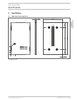
The modules may only be clamped to the long and short frame
sides in the permitted clamping area (see “Specification”/”Di-
mensions”).
When using the clamping method, for safety reasons apply an
anti-slip facility that is secured with screws to the lowest row of
modules.
Note
f
f
Also observe the installation instructions for the
frame system in this connection.
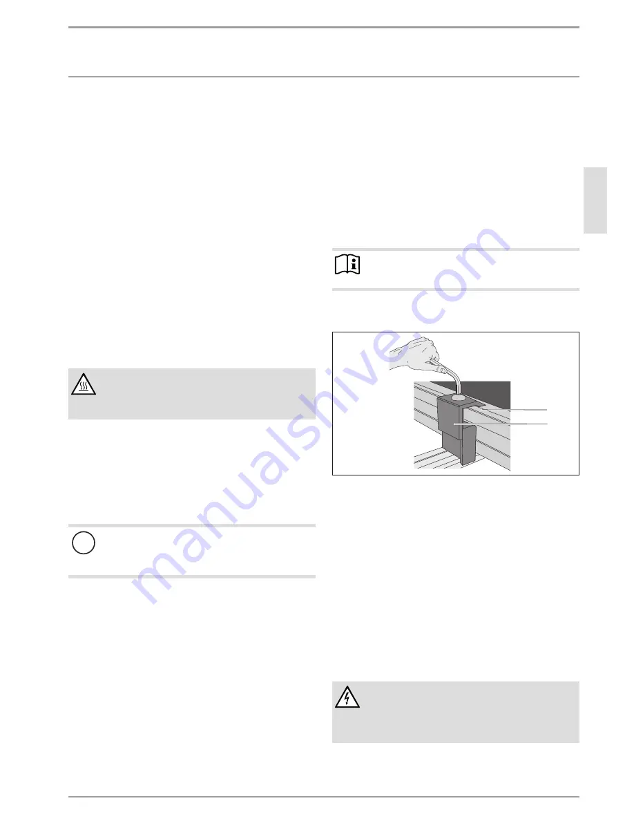
The clamping brackets must not protrude from the module frame
to the glass side.
D
00000
40
446
1
2
1 Module frame
2 Clamping bracket
f
f
Lay the module on the frame.
f
f
Clamp the module with the clamping bracket.
6.2 Power supply
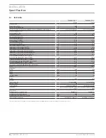
All relevant electrical values are given in chapter “Specification/
Data table”.
The module may, under normal operating conditions, exceed the
values specified on the type plate. To determine the rated voltage
values of components, multiply rated current values of cables and
fuse sizes, the specified values for the short circuit current and
off-load voltage by a factor of 1.25.
The PV modules meet the requirements of application category
A. They can be used in freely accessible systems with more than
50 V DC or 240 W output.
WARNING Electrocution
Never disconnect any connections under load.
Make sure there is sufficient protection against contact
with live components.
f
f
Only use insulated tools.


