INSTALLATION
Maintenance
14
| TEGREON 265-270 P www.stiebel-eltron.com
6.2.1 Connection in parallel and in series
Note
The requirements with regard to earthing must be
checked before commencing work in accordance with
the applicable regulations and standards.
f
f
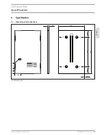
Observe the position of the earth hole in the chapter
“Specification”/”Dimensions”.
Modules of the same type may be connected in parallel or in
series.
!
Material losses
To avoid damage:
f
f
Only use modules of the same type and output for
series and parallel circuits.
f
f
When designing the wiring, you must observe all
electrical limit values for components connected to
the system. This applies primarily to the number of
modules connected in series or in parallel.
f
f
Ensure that the polarity is correct.
The switch panel is located at the back of the module:
D
00000
45
21
2
2
4
1
3
1 Switch panel
2 Connecting cable
3 Plug
4 Socket
f
f
Remove the plug and socket from the retainer.
f
f
Connect the plug of this module with the socket of the next
module.
D
00000
45
21
3
f
f
Connect the plug or socket of the first and last module in the
electrical line to the inverter cable.
6.2.2 Earth
You can secure an earth cable via the holes in the frame (see
chapter “Specification”/”Dimensions”).
7. Maintenance
The modules are low-maintenance. We recommend an annual
visual inspection.
f
f
Also check the mechanical and electrical connections for
damage.
Dirt on the modules reduces the output and yield. If the modules
are installed at an angle of inclination of more than 15°, rain is
generally sufficient to clean them.
!
Material losses
To avoid damage caused by scratching or high temper-
ature differentials:
f
f
Use exclusively liquid neutral cleaning agents to
clean modules.
f
f
Never use scouring or abrasive cleaning agents.
f
f
Only use water matched to the temperature of the
module surface.
f
f
Wipe the module surface with water and a soft
cloth.
8. Dismantling
WARNING Electrocution
Never disconnect any connections under load.
Make sure there is sufficient protection against contact
with live components.
f
f
Only use insulated tools.
To make the photovoltaic system load-free:
f
f
Isolate the inverter from the mains on the AC side.
f
f
Disconnect the photovoltaic system from the inverter at the
disconnect point on the DC side.
f
f
Ensure that there is no electrical voltage in the system.
f
f
Dismantle the photovoltaic system in reverse order to its in-
stallation. Observe all safety instructions.


