background image

www.stiebel-eltron.com 

Ultronic  S/W | 

15

EN

GL

ISH

InStallatIon 


Safety

InStallatIon

7.  safety

Only a qualified contractor should carry out installation, commis-

sioning, maintenance and repair of the appliance.

7.1  general safety instructions

We guarantee trouble-free operation and operational reliability 

only if the original accessories and spare parts intended for the 

appliance are used.

7.2  regulations, standards and instructions


WARNING Electrocution

Carry out all electrical connection and installation work 

in accordance with relevant regulations.


WARNING Electrocution

Only use a permanent connection to the power supply. 

The appliance must be able to be separated from the 

power supply by an isolator that disconnects all poles 

with at least 3 mm contact separation.

!


Damage to the appliance and environment

Observe the type plate. The specified voltage range must 

match the mains voltage.


Note

Observe all applicable national and regional regulations 

and instructions.

8.  Preparations

8.1  installation wall


Note

Observe the information in chapter "Operation / Safety".

Always install the appliance on a vertical wall. 
The back panel of the appliance must be flush with the wall to 

ensure that the appliance cannot be pulled off. 

f

f

Ensure that the wall on which the appliance is mounted is 

solid and has no recesses. 

8.2  installation in bathrooms


WARNING Electrocution

Install the appliance exclusively outside safety zone 2.

600

600

2250

3000

1

2

3

0

26

�0

7�

31

�0

16

7

0

Safety zone 0

1

Safety zone 1

2

Safety zone 2

3

Safety zone 3

f

f

Ensure that you maintain the safety clearances of safety 

zone 2 towards bath tubs and shower cubicles.

8.3  minimum clearances

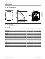
40

130

≥ 300

≥ 127

D

00000

19

93

7

f

f

Prior to installing the appliance, ensure the minimum per-

missible clearances to adjacent objects are observed.

f

f

Ensure that the ambient air can enter the inlet on the bottom 

of the appliance without obstruction.

f

f

Ensure that the air can escape from the appliance without 

obstruction.

Summary of Contents for Ultronic S

Page 1: ... installation Bediening en installatie Obsluha a instalace Obsługa i instalacja Обслуживание и Установка Használati és telepítési útmutató Händetrockner Hand dryer Sèche mains Handendroger Osoučeč rukou Suszarka do rąk Сушилки для рук Kézi szárító Ultronic S Ultronic W ...

Page 2: ...n the appliance 13 1 4 Units of measurement 13 2 Safety 13 2 1 Intended use 13 2 2 General safety instructions 13 2 3 Safety clearances 14 2 4 CE designation 14 2 5 Test symbols 14 3 Appliance description 14 4 Operation 14 5 Cleaning care and maintenance 14 6 Troubleshooting 14 Installation 7 Safety 15 7 1 General safety instructions 15 7 2 Regulations standards and instructions 15 8 Preparations ...

Page 3: ...mbol Appliance disposal Appliances with this marking are not suitable for general waste disposal and should therefore be collected and dis posed of separately 1 4 Units of measurement Note All measurements are given in mm unless stated oth erwise 2 Safety 2 1 Intended use The appliance is used to dry wet hands This appliance is designed for domestic use It can be used safely by untrained persons T...

Page 4: ...nce description The appliance works without contact If you hold your hands in the IR sensor detection range the appliance fan is automatically enabled Heated air is discharged from the appliance at high speed Any moisture left on your hands is removed and your hands are dried When you move your hands away from the IR sensor detection range the appliance stops automatically after approx 3 seconds 4...

Page 5: ...age Note Observe all applicable national and regional regulations and instructions 8 Preparations 8 1 Installation wall Note Observe the information in chapter Operation Safety Always install the appliance on a vertical wall The back panel of the appliance must be flush with the wall to ensure that the appliance cannot be pulled off f f Ensure that the wall on which the appliance is mounted is sol...

Page 6: ...pliance at the bottom f f Lift the casing cover up until the cover s fixing eyes have come free of the hooks on the appliance back panel f f Pull the casing cover forwards to remove it from the appliance 9 2 Wall mounting You can find a drilling template in the appendix to these instruc tions f f When positioning the drilling template be aware of the loca tion and length of the power cable see cha...

Page 7: ...he appliance to the wall with the 2 upper fixing screws and then tighten the 2 lower screws f f Connect the appliance to the power supply according to the wiring diagram see chapter Specification Wiring diagram 9 4 Assembling the casing cover 1 2 3 26_07_32_0042 f f Push the casing cover on to the appliance from the front f f Place the top of the casing cover on the back panel of the appliance so ...

Page 8: ... detection range 40 130 300 127 D0000019937 1 1 IR sensor detection range 11 3 Guidelines for installation height Note Height mm indicates the clearance between the bottom of the appliance and the floor Age Age Height mm Adult man 1350 Adult woman 1250 Nursery school 4 7 810 Primary school 7 10 910 High school 10 13 1120 High school 13 16 1250 ...

Page 9: ...PE 220 240V 1 N PE 220 240V Frequency Hz 50 60 50 60 Rated voltage V 230 230 Rated current A 4 0 4 0 Rated output W 910 910 Max mains impedance Zmax to DIN EN 61000 3 11 Ohm 257 257 Dimensions Height mm 289 289 Width mm 257 257 Depth mm 234 234 Weights Weight kg 4 4 4 4 Versions Colour Stainless steel off white RAL 9003 Casing material Diecast aluminium Diecast aluminium IP Rating IP24 IP24 Protec...

Page 10: ...nly be issued by those subsidiaries Such warranties are only granted if the subsidiary has issued its own terms of warranty No other warranty will be granted We shall not provide any warranty for appliances acquired in countries where we have no subsidiary to sell our products This will not affect warranties issued by any importers Environment and recycling We would ask you to help protect the env...

Page 11: ......

Page 12: ...em with the unit 8 3 The name address and contact details such as phone number and e mail address of the owner 8 4 The address where the unit is installed and the location e g in living room 8 5 The serial number of the unit 8 6 The date of purchase of the unit and the name of the seller of the unit 8 7 The date of installation of the unit where appropriate 8 8 A copy of the certificate of complia...

Page 13: ...hnician is safe and free from obstruction 14 Our authorised service technician may refuse to inspect and test the unit until you provide safe and free access to it at your cost 15 If we reject your warranty claim in accordance with clause 11 we may charge you for our authorised service technician s labour costs to inspect and test the unit 16 In order to properly test the unit we may remove it to ...

Page 14: ...nakuja 1 04600 Mäntsälä Tel 020 720 9988 info stiebel eltron fi www stiebel eltron fi France STIEBEL ELTRON SAS 7 9 rue des Selliers B P 85107 57073 Metz Cédex 3 Tel 0387 7438 88 Fax 0387 7468 26 info stiebel eltron fr www stiebel eltron fr Hungary STIEBEL ELTRON Kft Gyár u 2 2040 Budaörs Tel 01 250 6055 Fax 01 368 8097 info stiebel eltron hu www stiebel eltron hu Japan NIHON STIEBEL Co Ltd Kowa K...

Reviews: