INSTALLATION
Installation
www.stiebel-eltron.com
VRL-C 300/625/870 |
27
EN
GL
ISH
5.9
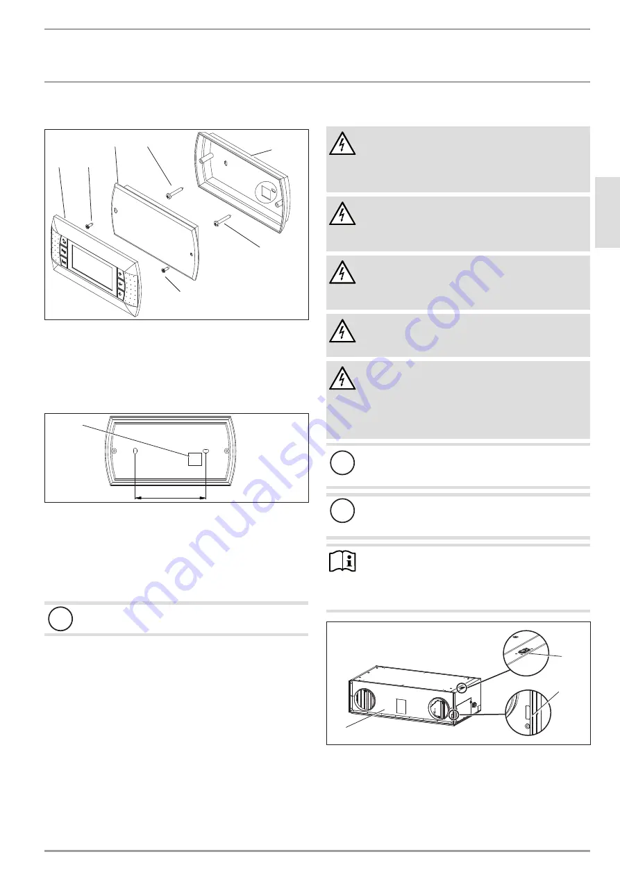
Installing the programming unit
D
00000
9
6
5
4
0
2
1
3
4
4
5
2
1 Wall mounting bracket
2 Flat-head self-tapping screw
3 Electronics module
4 Self-tapping screw
5 Fascia
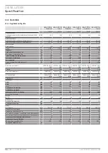
Wall mounting
84
D
00000
9
6
5
4
2
1
1 Cable entry
f
Remove the cover and the electronics module from the wall
mounting bracket.
f
Route the programming unit connecting cable through the
cable entry in the wall mounting bracket.
f
Secure the wall mounting bracket to the wall with two
screws.
!
Material losses
Ensure that the connecting cable is zero volt.
f
Connect the connecting cable to the back of the electronics
module.
f
Press the electronics module into the wall mounting bracket
until it clicks into place. Secure the electronics module using
the two screws provided.
f
Press the cover onto the electronics module until it clicks into
place.
Safety equipment for stove/fireplace operation
f
Install the safety equipment in such a way that it interrupts
the appliance power supply when required.
5.10 Electrical connection
WARNING Electrocution
Only qualified contractors may carry out the connec-
tion in accordance with these instructions. Carry out all
electrical connection and installation work in accordance
with national and regional regulations.
WARNING Electrocution
Do not install the appliance if it is damaged and there is
a risk that live components could be touched.
f
Check the appliance for external damage.
WARNING Electrocution
Before any work on the appliance, isolate the connecting
cables in the control panel. Secure the power supply
against unintentional reconnection.
WARNING Electrocution
Use RCDs of type A or B tripping on residual pulsating
direct current.
WARNING Electrocution
The appliance is delivered with a power cable with a
standard plug. In the case of a permanent connection,
the appliance must be able to be separated from the
power supply by an isolator that disconnects all poles
with at least 3 mm contact separation.
!
Material losses
Observe the fuse protection required for the appliance
(see chapter "Specification / Data table").
!
Material losses
The specified voltage must match the mains voltage. Ob-
serve the type plate.
Note
f
Observe the wiring diagram. See chapter "Specifica-
tion".
f
Never make any modifications to the internal equip-
ment electrics or controls.
D
00000
9
6
4
3
4
1
2
3
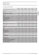
1 Rear
2 Condensate and cable entry (top)
3 Condensate and cable entry (back)
In the delivered condition, the power cable and cables for external
control components are routed out of the appliance through the
cable entry at the top.


