EN - 9
NOTE
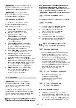
On the guard of the cutting
means there is the following symbol:
It indicates the
rotation direction of
the cutting means.
5. CONTROLS
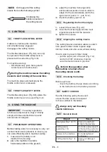
5.1 THROTTLE CONTROL LEVER
It allows to start/stop the machine
and simultaneously engages/
disengages the cutting means.
The throttle safety lever (Fig. 6.A) can only
be operated if the throttle safety lever is
pressed at the same time (Fig. 6.B).
For machine start up:
– Simultaneously push the regulator
control lever and safety lever.
Starting the machine causes the cutting
means to start rotating at the same time.
The machine stops automatically as the
throttle control lever is released.
5.2 THROTTLE SAFETY LEVER
The
throttle safety lever (Fig. 6.B) allows the
throttle control lever to be used (Fig. 6.A).
6. USING THE MACHINE
IMPORTANT
The safety regulations
to follow are described in chap. 2. Strictly
comply with these instructions to avoid
serious risks or dangers.
6.1 PRELIMINARY OPERATIONS
Before starting work
it is necessary to carry out
several checks and operations to ensure you
can work efficiently and in maximum safety:
1.
make sure the battery is not
inserted in its housing;
2.
place the machine in a stable
horizontal position on the ground;
3.
adjust the machine from ergonomic
and functional points of view in order to
adapt it to the worker stature and to the
type of work (par. 6.1.1 - par. 6.1.2);
4.
check the battery (par. 6.1.3).
6.1.1
Regulating the front hand grip
1.
Loosen the screws (Fig. 4.C)
2.
move the front hand grip into the most
ergonomic position for the operator;
3.
tighten the screws.
6.1.2 Aligning the cutting means
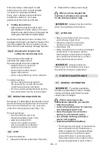
The cutting means orientation allows to switch
from grass trimmer mode to grass edge
trimmer mode, and vice versa, while working.
How to work in grass trimmer mode:
– pull the upper part of the rod (Fig. 7.A)
and turn it 180° clockwise, making
sure it remains locked in position.
Perform this operation when
the machine is turned off and
the cutting means is still.
6.1.3
Checking the battery
Before each use:
– check the battery charge status according
to the instructions in the battery booklet.
6.2 SAFETY CHECKS
Run the following safety checks and
ensure that the results correspond
to those outlined in the tables.
Always carry out the safety
checks before use.
6.2.1
General check
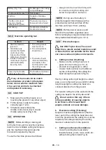
Object
Result
Hand grips (Fig. 1.E,1.F)
Clean, dry and fixed
firmly to the machine.
Cutting means
guard (Fig. 1.D)
Correctly and securely fit
to the machine, not worn/
deteriorated or damaged.
Screws on the machine
Correctly tightened
(not loose)
Cutting means (Fig. 1.C) Clean, not damaged
or worn
Summary of Contents for LT 40 Li
Page 4: ...G E A F B D H C1 1 2 dB LWA 1 2 7 6 3 4 8 5 Art N Type s n V 9 ...
Page 5: ...A E C B B D A C B 3 4 B D C A A B 5 6 A 7 8 ...
Page 6: ...9 10 A B B A 11 12 B A A 13 14 ...
Page 7: ...B A C A B A C B 15 16 C A B 17 18 19 ...
Page 151: ...EN 17 ...
Page 495: ...ST S p A Via del Lavoro 6 31033 Castelfranco Veneto TV ITALY dB LWA Type s n Art N ...


