background image

EN - 13

2. 

switch off the engine by turning 

the ignition key to Off;

3. 

with the engine turned off, close the 

fuel tap (fig. 22.A) (if provided).

4. 

remove the key from the ignition

 IMPORTANT 

  To keep the battery 

charged, do not leave the ignition key 

in the «on» or «headlights on» position 

when the engine is not running.

 The engine may be very warm 

immediately after it is shut off. Do not 

touch the  exhaust or adjacent parts. 

This can cause burn injuries.

 6.7  AFTER OPERATION

1. 

Allow the engine to cool before 

storing in an enclosed space.

2. 

Clean (par. 7.5).

3. 

Lower the cutting-means assembly, shift 

to neutral, engage the parking brake, 

turn off the engine and remove the 

ignition key (checking that all moving 

parts are completely stationary):


– whenever the machine is left unattended, 

the operator dismounts from the 

driving seat, or parks the machine;

7.  ROUTINE MAINTENANCE

 7.1  GENERAL INFORMATION

  The safety regulations to follow 

are described in chap. 2. Strictly 

comply with these instructions to 

avoid serious risks or hazards.

  Before conducting any inspections, 

cleaning or maintenance/adjustment 

interventions on the machine:

•  disengage the cutting means;

•  shift into neutral;

•  engage the parking brake;

•  stop the engine;

• 

remove the key, (never leave the 

keys in the ignition or within reach of 

children or unauthorised persons);

•  make sure that all moving parts 

have come to a complete stop;

•  read the relevant instructions;

• 

Use suitable clothing, protective 

gloves and goggles

• 

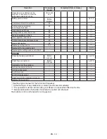
The frequency and types of maintenance are 

summarised in the "Maintenance Table". The 

table will help you maintain your machine’s 

safety and performance. It lists the main 

maintenance tasks and how often they need 

to be performed. Carry out the relevant task 

as soon as it is scheduled to be performed.

•  The use of non-genuine and/or incorrectly 

assembled spare parts and attachments 

could adversely affect machine operation 

and safety. The manufacturer shall 

decline all liability in the event of injuries 

or damages caused by such parts.

•  Genuine spare parts are supplied by 

authorized assistance workshops and dealers.

 7.2  REFUELLING  / EMPTYING 

THE FUEL TANK

 NOTE 

  The type of fuel to use is 

given in the engine manual.

 IMPORTANT 

  The machine is delivered 

to the client without fuel. Follow all the 

instructions in the engine manual.

 7.2.1  Refuelling

To refuel:

1. 

Unscrew the tank closure cap 

and remove it (fig. 

22)

.

2. 

Insert the funnel (fig. 23).

3. 

Refuel being careful not to 

completely fill the tank.

4. 

Remove the funnel.

5. 

Close the fuel cap securely after 

refuelling and clean away any spills.

 IMPORTANT 

  Do not drip petrol onto 

the plastic parts to avoid ruining them. 

In the event of accidental leaks, rinse 

immediately with water. The warranty does 

not cover for damage to plastic parts of the 

bodywork or the engine caused by petrol.

 7.2.2  Emptying the fuel tank

 NOTE 

  Fuel is perishable and should 

not remain in the tank for more than 30 

days. Empty the fuel tank before storing the 

machine for long periods of time (chap. 9).

  Allow the engine to cool 

before emptying the fuel tank.

1. 

Place the machine on a flat 

surface, in the open air.

2. 

Place a suitable container under 

the drain tube (fig. 25.A).

Summary of Contents for SDNSL 108 Hydro

Page 1: ...nducente a bordo seduto MANUALE DI ISTRUZIONI ATTENZIONE prima di usare la macchina leggere attentamente il presente libretto EN Ride on lawnmower with seated operator OPERATOR S MANUAL WARNING read thoroughly the instruction booklet before using the machine ...

Page 2: ......

Page 3: ...ITALIANO Istruzioni Originali IT ENGLISH Translation of the original instruction EN ...

Page 4: ...D F C E B H G A kW min s n 7 5 4 1 kg 3 2 6 Type Art N Transmission 8 max xxx N xx kg max xxx N xxx kg 1 2 ...

Page 5: ...5 3 A B C D E A F G H A A B C 4 B C C A 6 A B C D E ...

Page 6: ...7 I II A C C B OK NO A B C D D E F F G G 8 9 ...

Page 7: ...10 A B B C C 11 B 2 A C B 2 A D C B D 1 E D E 1 A B B 1 B B ...

Page 8: ...12 J A B C D E E 1 F G H I L E F II I 13 14 A A ...

Page 9: ...15 A B 16 B A 17 A H H 30 mm H 10 mm H 20 mm H 0 mm A C B D 18 max 10 17 19 A 20 1 3 21 A B ...

Page 10: ...22 A 23 24 25 B C A ...

Page 11: ...27 A B C A B C A 26 I II A A 28 29 A A B C ...

Page 12: ...A 110 mm 30 31 32 33 B A C C 34 A D B C 35 A B A A B C ...

Page 13: ...36 A A 37 38 B C D A2 ...

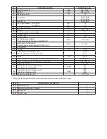
Page 14: ... min 1 km h 0 8 8 15 Dimensioni 16 Lunghezza mm 1697 17 Larghezza con deflettore di scarico laterale Larghezza senza deflettore di scarico laterale 1312 1101 18 Altezza mm 1098 19a Codice dispositivo di taglio per funzione scarico laterale dell erba 82004370 0 19b Codice dispositivo di taglio per funzione mulching 1134 9231 01 20 Capacità del serbatoio carburante l 6 5 8 5 21 Limite di carico per ...

Page 15: ...proximate at 3000 min 1 km h 0 8 8 15 Dimensions 16 Length mm 1697 17 Width with side discharge chute Width without side discharge chute 1312 1101 18 Height mm 1098 19a Cutting means code for grass side discharge function 82004370 0 19b Cutting means code for Mulching function 1134 9231 01 20 Fuel tank capacity l 6 5 8 5 21 Admissible load on towing device maximum vertical weight N kg 245 25 22 Ad...

Page 16: ... Cutting means engage and disengage functions 9 5 8 Reverse gear cutting consent button 9 5 9 Cutting height adjuster lever 9 5 10 Hour meter 9 6 USING THE MACHINE 9 6 1 Preparation 9 6 2 Safety checks 10 6 3 Using on slopes 11 6 4 Startup 11 6 5 Operation 11 6 6 Stop 12 6 7 After operation 13 7 ROUTINE MAINTENANCE 13 7 1 General information 13 7 2 Refuelling emptying the fuel tank 13 7 3 Check to...

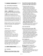
Page 17: ...hese instructions to use the machine Local regulations may restrict the age of the operator Never use the machine if the user is tired or unwell or has taken medicine drugs alcohol or any substances which may slow his reflexes and compromise his judgement Do not allow children or other passengers to ride on the machine Bear in mind that the operator or user is responsible for accidents or unexpect...

Page 18: ...han could limit visibility Be very careful near ravines ditches or embankments The machine could overturn if a wheel slides over the edge or if the earth gives way Pay attention on sloping ground which requires particular care to prevent overturning or loss of control of the machine The main reasons for loss of control are Insufficient wheel grip Excessive speed Inadequate braking Type of machine ...

Page 19: ...uld reach a naked light a spark or a strong heat source To reduce fire risks do not leave containers with debris inside a room 2 5 ENVIRONMENTAL PROTECTION Safeguarding the environment must be a relevant and priority aspect of machine use of benefit to the community and the environment we live in Avoid being a disturbance to the neighbourhood Use this machine at reasonable times of the day only no...

Page 20: ...y consumers i e non professional operators The machine is intended for DIY use only IMPORTANT The machine must be used by one operator 3 2 SAFETY SIGNS The machine has various symbols on it fig 2 They are used to remind the operator of the behaviour to follow to use it with the necessary attention and caution Meaning of symbols Warning Read the instruc tions before operating the machine Warning Di...

Page 21: ...with these instructions to avoid serious risks or hazards For storage and transport purposes some components of the machine are not installed in the factory and have to be assembled after unpacking Follow the instructions below Unpacking and completing the assembly should be done on a flat and stable surface with enough space for machine handling and its packaging always making use of suitable equ...

Page 22: ...ion of assembly indicated in the figure R right L left 2 fully tighten the screws fig 8 D 3 Attach the front bumper fig 8 E to the brackets fig 8 A and fig 8 B using the screws fig 8 F and nuts fig 8 G 4 6 MOUNTING THE CUTTING MEANS ASSEMBLY SIDE REINFORCEMENTS IF FORESEEN Complete the mounting of the cutting means assembly by fitting the side reinforcements on the cutting means assembly profile u...

Page 23: ...during grass cutting operations 2 Minimum engine speed Used when the machine is sufficiently warm during stationary periods of operation NOTE When moving from one area to another put the lever in a position between tortoise and hare 5 3 PARKING BRAKE LEVER This lever stops the machine from moving when it has been parked This lever has two positions fig 12 D corresponding to 1 Brake disengaged Pres...

Page 24: ...ed without causing the engine to stop 5 9 CUTTING HEIGHT ADJUSTER LEVER Use this lever to raise and lower the cutting means assembly to one of the 7 different cutting heights fig 12 G The seven positions for this lever shown as 1 to 7 on the label correspond to various cutting heights between 3 and 8 cm To go from one position to another move the lever sideways and put it back in one of the stop n...

Page 25: ...eels as indicated par 7 4 6 2 SAFETY CHECKS Run the following safety checks and check that the results correspond to those outlined on the tables Always carry out the safety checks before use 6 2 1 General safety check Object Result Battery No damage to the casing cover or terminals Side discharge guard Good condition No damage Properly installed Fuel lines and connections No leaks Electrical cabl...

Page 26: ... means par 5 7 5 Engage the parking brake par 5 3 6 Shift the throttle control to maximum hare speed position par 5 2 7 If cold starting engage the choke par 5 2 8 Insert the ignition key and turn to On to make electrical contact then turn it to Start to start the engine 9 Release the ignition key once the engine has started 10 If cold starting as soon as the engine ticks over regularly 10a Diseng...

Page 27: ...ss and weeds start growing clover and daisies etc 2 It is always better to cut the grass when dry 3 The cutting means must be in good condition and well sharpened so that the grass is cut straight without a ragged edge that leads to yellowing at the ends 4 The engine must run at full speed both to ensure a sharp cut of the grass and to get the necessary thrust to push the cuttings through the coll...

Page 28: ...nd types of maintenance are summarised in the Maintenance Table The table will help you maintain your machine s safety and performance It lists the main maintenance tasks and how often they need to be performed Carry out the relevant task as soon as it is scheduled to be performed The use of non genuine and or incorrectly assembled spare parts and attachments could adversely affect machine operati...

Page 29: ...suitable vessel 5 Replace the drain plug fig 26 B making sure that the gasket is in the right position fig 26 C 6 Fully tighten holding the extension tube firmly in place fig 26 A 7 Clean up any spills Type II 1 Unscrew the topping up cap fig 26 A 2 Fit the tube fig 26 B onto the syringe fig 26 C and insert it as far as possible into the hole 3 Using the syringe fig 26 C suck up all the engine oil...

Page 30: ...ntained The machine battery must always be charged before using the machine for the first time after purchase before leaving the machine disused for a long period over 30 days par 9 before starting up the machine after a prolonged period of inactivity Carefully read and observe the battery recharging instructions in the booklet provided with the battery Failure in following the procedure or in cha...

Page 31: ...ting position near the wheel to be changed par 8 3 2 par 8 3 3 Check that the jack is perfectly perpendicular to the ground 8 3 2 Choice and positioning of the jack on the rear wheels Position some wooden wedges fig 29 A to the wheel base fig 29 B to the side of the wheel to be changed fig 29 C The maximum possible jack height when closed is 110 mm fig 0 Position the jack under the rear axle in th...

Page 32: ... have a bayonet fitting and are installed in the bulb holder which can be taken out by turning it anti clockwise with pliers fig 37 8 7 REAR AXLE This is a sealed single unit that does not require maintenance It is permanently lubricated and its lubricant does not need changing or topping up 9 STORING THE MACHINE When you intend to put your machine away for more than 30 days 1 Wait for the engine ...

Page 33: ...overs all material and manufacturing defects The user must follow all the instructions provided in the accompanying documentation The warranty does not cover damages caused by Failure to become familiar with the documentation accompanying the machine Carelessness Incorrect or prohibited use or assembly Use of non genuine spare parts Use of attachments not supplied or approved by the manufacturer T...

Page 34: ...eans 100 Replacing the transmission belt Replacing the cutting means control belt ENGINE Checking topping up fuel level Before each use par 7 2 Check top up engine oil Before each use par 7 3 Replacement of the engine oil Air filter cleaning and check Air filter replacement Fuel filter check Fuel filter replacement Spark plug points cleaning and check Replace the spark plug See the engine manual f...

Page 35: ...ave the correct gap 3 Starting is difficult or the engine runs erratically carburation problems clean or replace the air filter empty the fuel tank and refill with fresh fuel check and replace the fuel filter if necessary 4 Weak engine performance during cutting forward speed too high in relation to cutting height reduce the forward speed and or raise the cutting height par 6 5 4 5 The engine shut...

Page 36: ...2 The machine starts to vibrate abnormally and or has hit an object damaged or loose parts stop the machine and remove the ignition key inspect for damage check for and tighten any loose parts have all checks repair work and replacements carried out by a specialized Centre only If problems persist after having performed the above operations contact your dealer 15 ATTACHMENTS 15 1 MULCHING KIT It f...

Page 37: ...lati da diritto d autore E vietata ogni riproduzione o alterazione anche parziale non autorizzata del documento EN The content and images in this User Manual were produced expressly for STIGA S p A and are protected by copyright any unautho rised reproduction or modification to the document either partially or in full is prohibited ...

Page 38: ...STIGA S p A Via del Lavoro 6 31033 Castelfranco Veneto TV ITALY Type s n Art N stiga com ...

Reviews: