background image

READ  AND  FOLLOW  ALL  ASSEMBLY,  OPERATING, 
AND SAFETY  INSTRUCTIONS  CAREFULLY.    AT  LEAST
TWO  (2) ADULTS ARE NEEDED TO PUT THIS TABLE 
TOGETHER!

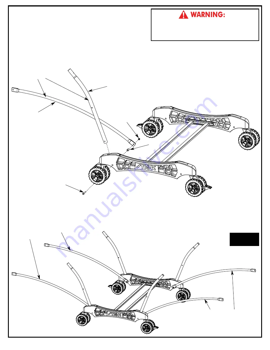
3. 

Attach four Strut Tubes (

#4

) and four Linkage Tubes 

    (

#25

) to Caster Beam Assembly using four Carriage 

    Bolts (

#10

), four Spacers (

#11

) and four Locknuts (

#14

)

    as shown in 

FIGURE 3

.


Snug, but do not overtighten the #14 Locknuts as 

    this is a pivot point.

Parts Needed:

4 pcs - 

#4

 Strut Tube

4 pcs - 

#25

 Linkage Tube

Figure 3

Hardware Needed:

4 pcs - 

#10

 Carriage Bolt

4 pcs - 

#11

 Spacer  

4 pcs - 

#14

 Locknut

5

10

11

14

4

25

NOTE: make sure
linkage tube is arched
in this direction.

NOTE: make sure
linkage tube is arched
in this direction.

NOTE: make sure
linkage and Strut tube 
are turned as shown.

Summary of Contents for T8562

Page 1: ...er parts may be shipped inside larger parts Check inside all parts and cartons before assembling or ordering parts 3 Do not tighten hardware until instructed to do so If hardware is tighten too soon m...

Page 2: ...d of three 3 years from the original purchase WARRANTY COVERAGE ESCALADE SPORTS warrants to the original Consumer Purchaser that any Product of its manufacture is free from defects in material and wor...

Page 3: ...RDWARE IDENTIFICATION 12 1 4 20 Nylon locknut 16 pieces 1 4 20 X 2 1 4 Phillips Pan Head Screw 4 pieces 17 10 24 X 2 1 2 Phillips Pan Head Screw 4 pieces 10 24 X 3 4 Thumb Screw 4 pieces 1 4 20 X 2 3...

Page 4: ...TOGETHER 1 Slide a Caster Wheel with Lock 13 into Caster Beam as shown in FIGURE 1 On the other end of the Caster Beam attach a Caster Wheel without Lock 9 Make sure you have one Caster Wheel with lo...

Page 5: ...Spacers 11 and four Locknuts 14 as shown in FIGURE 3 Snug but do not overtighten the 14 Locknuts as this is a pivot point Parts Needed 4 pcs 4 Strut Tube 4 pcs 25 Linkage Tube Figure 3 Hardware Neede...

Page 6: ...Nut 27 to each Leg Leveler 28 Then install Leg Levelers to Square Legs as shown in FIGURE 4 Repeat for other Table Top Parts Needed 2 pcs 1 Square Leg Silver 1 pc 2 Aluminum Top Assembly 2 pcs 28 Leg...

Page 7: ...BASE HANDLE TOP ASSEMBLIES BY GRASPING ONLY THE TOPS THEMSELVES DO NOT GRASP METAL LEGS U SUPPORT LINKAGE OR HINGES THESE PARTS CAN MOVE AND COULD PINCH FINGERS OR HANDS CAUSING SERIOUS INJURY ASSEMBL...

Page 8: ...cknuts 14 as shown in FIGURE 6 D Attach two Corner Protectors 29 to Top Assembly using four Screws 15 with four Washers 37 as shown in FIGURE 6 Repeat for other Table Top Figure 6 Hardware Needed 4 pc...

Page 9: ...point until the plastic clips are engaged Then continue lifting until closed 3 Raise other table half in the same manner See Figure 9 Figure 9 PLAYBACK POSITION Plastic Clip PLAYING POSITION STORAGE P...

Page 10: ...ch Tabs Bead Cord Sleeve Height adjustment slot A B C Net System Description 2 Adjustments A Adjust overall net tension by slightly loosening the knob and moving net post assembly Moderately tighten k...

Page 11: ...5 15 16 5 12 11 4 15 14 10 10 8 22 15 15 26 26 26 26 8 10 13 9 10 12 9 13 7 12 5 11 4 14 11 14 15 25 5 28 27 1 20 37 17 15 35 15 35 15 25 14 11 12 5 18 4 3 34 34 15 15 16 16 15 15 37 29 15 37 29 2A 28...

Page 12: ...ounting Bracket 1 4 Plastic Washer Linkage Tube Silver 10 24 X 3 4 Thumb Screw M12 Hex Nut Leg Leveler M12 Threads Corner Protector 1 Molded Tube Bracket 1 Plastic Clip This Owner s Manual 10 Washer 2...

Page 13: ...cada paso 2 Algunas partes peque as pueden estar empacadas dentro de las partes grandes Verifique en el interior de todas las partes y cartones antes de ensamblar o solicitar partes 3 No ajuste las pa...

Page 14: ...N DE LA GARANT A Se garantiza este Producto al comprador original por un per odo de 3 a os a partir de la fecha de compra COBERTURA DE LA GARANT A ESCALADE SPORTS le garantiza al comprador original qu...

Page 15: ...ca de Seguridad 16 Piezas 1 4 20 X 2 1 4 Tornillo Phillips 4 Piezas 17 10 24 X 2 1 2 Tornillo Phillips 4 Piezas 10 24 X 3 4 Tornillo de Mariposa 4 Piezas 1 4 20 X 2 3 4 Tornillo de Carruaje 4 Piezas 1...

Page 16: ...ta el paso para el segundo Carril 2 Deslice el Tubo Horizontal de Soporte 7 dentro del los Carriles 8 y atornille utilizando cuatro Tornillos de Mariposa 26 como se muestra en la FIGURA 2 ADVERTENCIA...

Page 17: ...LAR LA MESA 3 Instale cuatro Tubos Estructurales 4 y cuatro Tubos Conectores 25 a el Carril ensamblado utilizando cuatro Tornillos de Carruaje 10 cuatro Separadores de Plastico 11 y cuatro Tuercas de...

Page 18: ...brazaderas 6 utilizando dos Tornillos Hexagonales 21 cuatro Rondanas de Pl stico 24 y dos Tuercas de Seguridad 14 como se muestra en la FIGURA 4 y DETALLE A Instale las Patas Cuadradas 1 a los Soporte...

Page 19: ...UEDEN MOVERSE Y PODR AN LASTIMAR LOS DEDOS O LAS MANOS CAUSANDO LESIONES GRAVES POR FAVOR ENSAMBLE LA MESA COMO SE MUESTRA CON LAS PATAS COMPLETAMENTE CERRADAS Y EL TABLERO EN POSICI N VERTICAL NO ABR...

Page 20: ...ina 6 pzs 15 Tornillo Phillips 4 pzs 37 Rondana 2 pzs 20 Tornillo Hexagonal NO ABRA LA MESA EN LA POSICI N DE JUEGO HASTA QUE AMBAS MITADES DE LA MESA EST N INSTALADAS NO DEJE LA MESA LEVANTADA SOLA P...

Page 21: ...como esta mostrado en la Figura 7B Bisagra Asegurada Clip de Pl stico POSICION DE JUEGO Figura 8 Figura 9 POSICION PARA GUARDAR Presione para asegurar bisagra PARA ABRIR 1 Sostenga la orilla de arriba...

Page 22: ...cie de juego asegurando firmemente el poste vertical en la ranura de ajuste de altura Coloque los soportes de la red con la rondana y manija como se muestra Nota Hay un soporte de la red izquierdo y u...

Page 23: ...5 15 16 5 12 11 4 15 14 10 10 8 22 15 15 26 26 26 26 8 10 13 9 10 12 9 13 7 12 5 11 4 14 11 14 15 25 5 28 27 1 20 37 17 15 35 15 35 15 25 14 11 12 5 18 4 3 34 34 15 15 16 16 15 15 37 29 15 37 29 2A 28...

Page 24: ...8 X 5 8 Tornillo Phillips 8 32 X 1 1 4 Tornillo Phillips 10 24 X 2 1 2 Conjunto de Red y Postes Tuerca de Seguridad 10 24 Tornillo Hexagonal 1 4 20 X 3 1 4 Tornillo Hexagonal 1 4 20 X 2 3 4 Soporte de...

Reviews: