background image

9

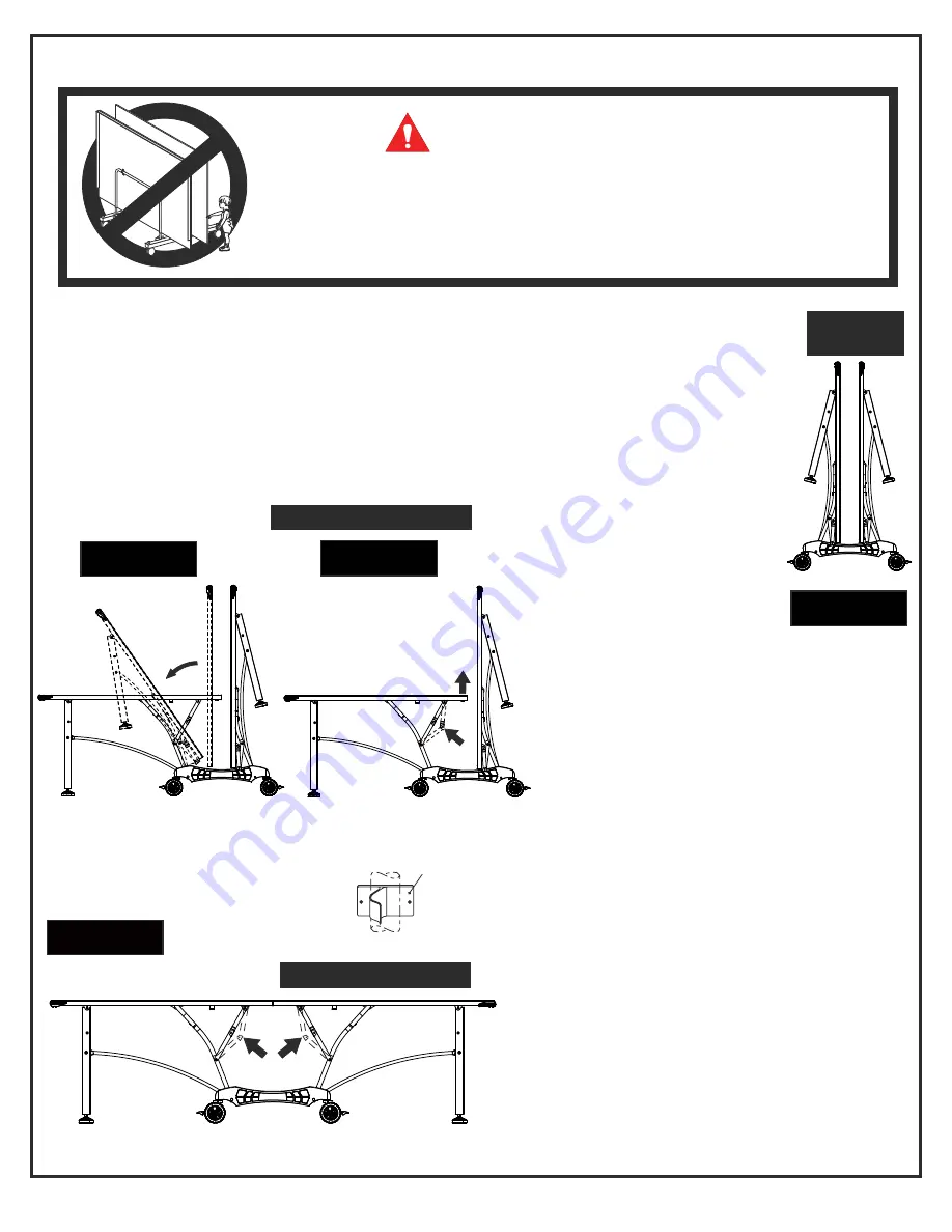
OPENING AND CLOSING INSTRUCTIONS

WARNING:

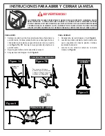
TO OPEN:

1.

Hold center of top edge.  Gently pull outward to midway 

       position.  Continue to pull until disengaged from plastic 
       clips and legs rest on the floor as shown in 

Figure 7A

 and


 7B

.  Do not leave table partially opened at midway position.

2.

    Lower second top as described in step 1.

3.

    Lock all four center hinges.  See 

Figure 8

.

Figure 7A

Figure 8

TO CLOSE:

1.

Unlock all four center hinges. See


 Figure 8

.

2.

Lift one table half to midpoint until

       the plastic clips are engaged.
       Then continue lifting until closed.

3.

Raise other table half in the same

       manner.  See 

Figure 9

.

Figure 9

PLAYBACK POSITION

Plastic
Clip

PLAYING POSITION

STORAGE
POSITION

Push to
lock hinge

Midway
Position

hinge
Locked

To lock hinge push up on
the table and push hinge
as shown in Figure 7B.

Figure 7B

WIND GUSTS CAN BLOW OVER OR UNEXPECTEDLY OPEN THE TABLE: STORE IN

PROTECTED AREA. EXERCISE CAUTION IN OPENING/CLOSING TABLE. SMALL

CHILDREN, OR CHILDREN NOT PROPERLY INSTRUCTED IN ITS USE, MUST NOT BE

ALLOWED TO OPEN/CLOSE TABLE. IMPROPER HANDLING AND MISUSE CAN RESULT IN

SERIOUS INJURY OR DAMAGE. DO NOT CLIMB, STAND, OR JUMP ON TABLE.

Summary of Contents for T8562

Page 1: ...er parts may be shipped inside larger parts Check inside all parts and cartons before assembling or ordering parts 3 Do not tighten hardware until instructed to do so If hardware is tighten too soon m...

Page 2: ...d of three 3 years from the original purchase WARRANTY COVERAGE ESCALADE SPORTS warrants to the original Consumer Purchaser that any Product of its manufacture is free from defects in material and wor...

Page 3: ...RDWARE IDENTIFICATION 12 1 4 20 Nylon locknut 16 pieces 1 4 20 X 2 1 4 Phillips Pan Head Screw 4 pieces 17 10 24 X 2 1 2 Phillips Pan Head Screw 4 pieces 10 24 X 3 4 Thumb Screw 4 pieces 1 4 20 X 2 3...

Page 4: ...TOGETHER 1 Slide a Caster Wheel with Lock 13 into Caster Beam as shown in FIGURE 1 On the other end of the Caster Beam attach a Caster Wheel without Lock 9 Make sure you have one Caster Wheel with lo...

Page 5: ...Spacers 11 and four Locknuts 14 as shown in FIGURE 3 Snug but do not overtighten the 14 Locknuts as this is a pivot point Parts Needed 4 pcs 4 Strut Tube 4 pcs 25 Linkage Tube Figure 3 Hardware Neede...

Page 6: ...Nut 27 to each Leg Leveler 28 Then install Leg Levelers to Square Legs as shown in FIGURE 4 Repeat for other Table Top Parts Needed 2 pcs 1 Square Leg Silver 1 pc 2 Aluminum Top Assembly 2 pcs 28 Leg...

Page 7: ...BASE HANDLE TOP ASSEMBLIES BY GRASPING ONLY THE TOPS THEMSELVES DO NOT GRASP METAL LEGS U SUPPORT LINKAGE OR HINGES THESE PARTS CAN MOVE AND COULD PINCH FINGERS OR HANDS CAUSING SERIOUS INJURY ASSEMBL...

Page 8: ...cknuts 14 as shown in FIGURE 6 D Attach two Corner Protectors 29 to Top Assembly using four Screws 15 with four Washers 37 as shown in FIGURE 6 Repeat for other Table Top Figure 6 Hardware Needed 4 pc...

Page 9: ...point until the plastic clips are engaged Then continue lifting until closed 3 Raise other table half in the same manner See Figure 9 Figure 9 PLAYBACK POSITION Plastic Clip PLAYING POSITION STORAGE P...

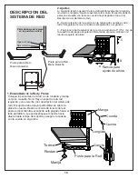
Page 10: ...ch Tabs Bead Cord Sleeve Height adjustment slot A B C Net System Description 2 Adjustments A Adjust overall net tension by slightly loosening the knob and moving net post assembly Moderately tighten k...

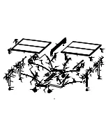
Page 11: ...5 15 16 5 12 11 4 15 14 10 10 8 22 15 15 26 26 26 26 8 10 13 9 10 12 9 13 7 12 5 11 4 14 11 14 15 25 5 28 27 1 20 37 17 15 35 15 35 15 25 14 11 12 5 18 4 3 34 34 15 15 16 16 15 15 37 29 15 37 29 2A 28...

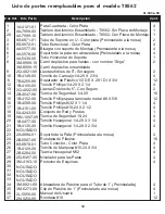
Page 12: ...ounting Bracket 1 4 Plastic Washer Linkage Tube Silver 10 24 X 3 4 Thumb Screw M12 Hex Nut Leg Leveler M12 Threads Corner Protector 1 Molded Tube Bracket 1 Plastic Clip This Owner s Manual 10 Washer 2...

Page 13: ...cada paso 2 Algunas partes peque as pueden estar empacadas dentro de las partes grandes Verifique en el interior de todas las partes y cartones antes de ensamblar o solicitar partes 3 No ajuste las pa...

Page 14: ...N DE LA GARANT A Se garantiza este Producto al comprador original por un per odo de 3 a os a partir de la fecha de compra COBERTURA DE LA GARANT A ESCALADE SPORTS le garantiza al comprador original qu...

Page 15: ...ca de Seguridad 16 Piezas 1 4 20 X 2 1 4 Tornillo Phillips 4 Piezas 17 10 24 X 2 1 2 Tornillo Phillips 4 Piezas 10 24 X 3 4 Tornillo de Mariposa 4 Piezas 1 4 20 X 2 3 4 Tornillo de Carruaje 4 Piezas 1...

Page 16: ...ta el paso para el segundo Carril 2 Deslice el Tubo Horizontal de Soporte 7 dentro del los Carriles 8 y atornille utilizando cuatro Tornillos de Mariposa 26 como se muestra en la FIGURA 2 ADVERTENCIA...

Page 17: ...LAR LA MESA 3 Instale cuatro Tubos Estructurales 4 y cuatro Tubos Conectores 25 a el Carril ensamblado utilizando cuatro Tornillos de Carruaje 10 cuatro Separadores de Plastico 11 y cuatro Tuercas de...

Page 18: ...brazaderas 6 utilizando dos Tornillos Hexagonales 21 cuatro Rondanas de Pl stico 24 y dos Tuercas de Seguridad 14 como se muestra en la FIGURA 4 y DETALLE A Instale las Patas Cuadradas 1 a los Soporte...

Page 19: ...UEDEN MOVERSE Y PODR AN LASTIMAR LOS DEDOS O LAS MANOS CAUSANDO LESIONES GRAVES POR FAVOR ENSAMBLE LA MESA COMO SE MUESTRA CON LAS PATAS COMPLETAMENTE CERRADAS Y EL TABLERO EN POSICI N VERTICAL NO ABR...

Page 20: ...ina 6 pzs 15 Tornillo Phillips 4 pzs 37 Rondana 2 pzs 20 Tornillo Hexagonal NO ABRA LA MESA EN LA POSICI N DE JUEGO HASTA QUE AMBAS MITADES DE LA MESA EST N INSTALADAS NO DEJE LA MESA LEVANTADA SOLA P...

Page 21: ...como esta mostrado en la Figura 7B Bisagra Asegurada Clip de Pl stico POSICION DE JUEGO Figura 8 Figura 9 POSICION PARA GUARDAR Presione para asegurar bisagra PARA ABRIR 1 Sostenga la orilla de arriba...

Page 22: ...cie de juego asegurando firmemente el poste vertical en la ranura de ajuste de altura Coloque los soportes de la red con la rondana y manija como se muestra Nota Hay un soporte de la red izquierdo y u...

Page 23: ...5 15 16 5 12 11 4 15 14 10 10 8 22 15 15 26 26 26 26 8 10 13 9 10 12 9 13 7 12 5 11 4 14 11 14 15 25 5 28 27 1 20 37 17 15 35 15 35 15 25 14 11 12 5 18 4 3 34 34 15 15 16 16 15 15 37 29 15 37 29 2A 28...

Page 24: ...8 X 5 8 Tornillo Phillips 8 32 X 1 1 4 Tornillo Phillips 10 24 X 2 1 2 Conjunto de Red y Postes Tuerca de Seguridad 10 24 Tornillo Hexagonal 1 4 20 X 3 1 4 Tornillo Hexagonal 1 4 20 X 2 3 4 Soporte de...

Reviews: