Release 00 - 03/2018
Engine TRE 224
page 5
Workshop Manual
The purpose of this manual is to provide to Service
Centres the information necessary for a correct
maintenance, dismantling and repair procedure
for engines TRE 224.
Interventions on the engine must be performed in
accordance with instructions in the following pages
and with safety regulations in force in the country in
which the engine is operated, and only by authori-
sed and appropriately trained personnel.
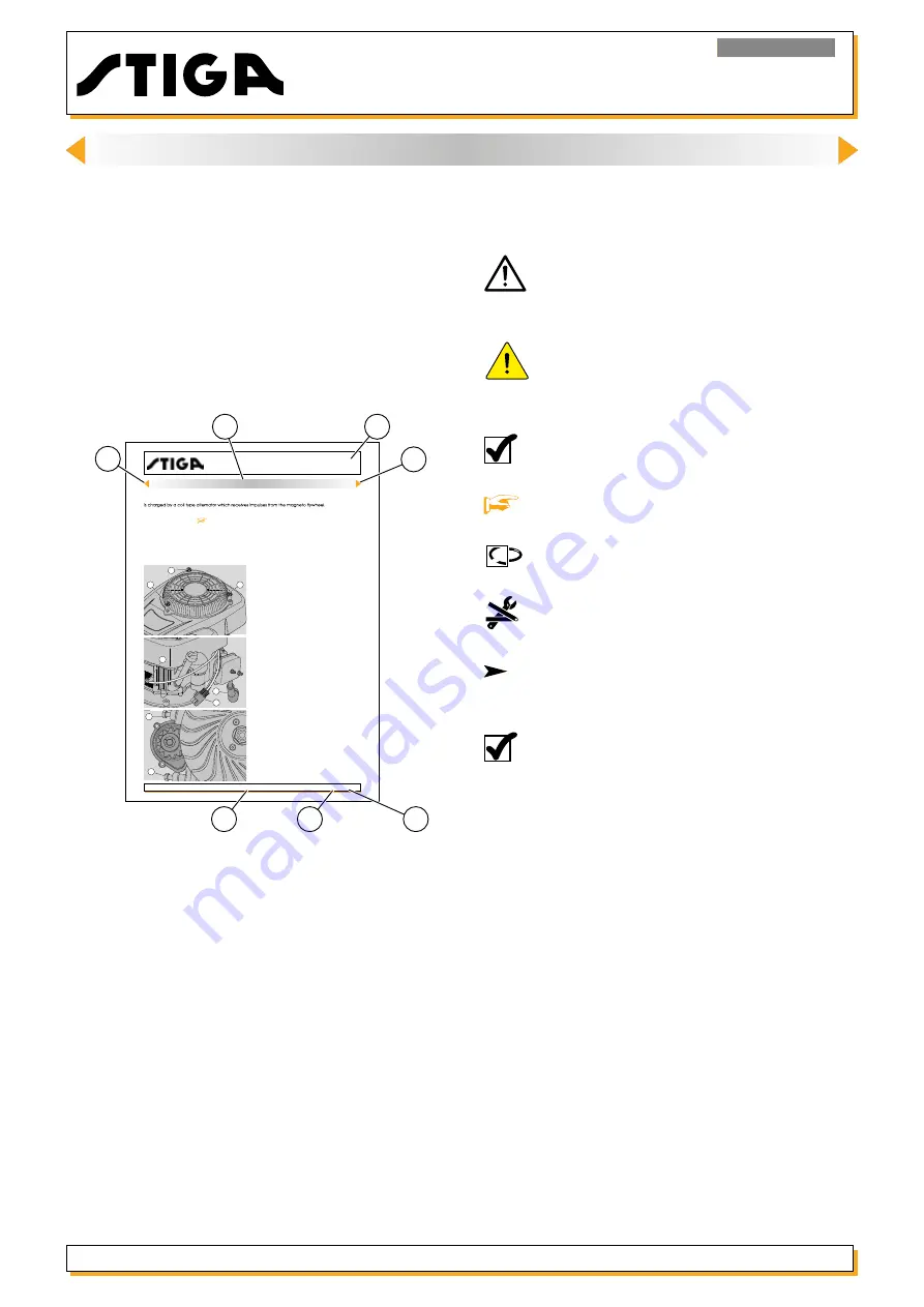
In every manual page the following informations
are described:
page 16
Release 00 - 03/2018
Engine TRE 224
Workshop Manual
General information
The starter system consists of a motor supplied by a 12 Volt battery (mounted on the machine). The battery
See the relevant section
[
16]
for advice on resolving problems due to the malfunctioning of the star-
ting system.
6. STARTING SYSTEM
3
2
6.1. Removing the starter motor
1 - Remove the cover by unscrewing the three
nuts (1).
2 - Disconnect the connector (2) from the wiring.
3 - Disconnect the live cable (3) and the earth
cable (4).
4 - Remove the two screws (5) and remove the
motor.
5 - To assemble repeat the operation in reverse.
When attaching the connector (2) the three wires
must attached in the proper places.
6 - Assemble the cover.
4
5
5
1
1
1
A: Motor typ for which the page is valid.
B: Reference to the chapter and the argument
with the relative numbering.
C: Presence of previous or following chapters from
the present chapter.
D: Issue date or possible audit.
E: Audit number.
F: Page progressive numbering.
Certain symbols are used in the manual, highlighting
particularly important information, risks, warnings
and prescriptions:
Warns of operations that should be carried
out with utmost care to avoid impairing the
functionality and safety of the lawnmower.
Warns of operations that should be carried
out with utmost care to avoid injury to the
operator.
NOTE: Refers to specific advice by the ma-
nufacturer.
Reference to another procedure or part of
the manual.
Recommends that washers and O-rings are
checked and replaced if necessary.
Refers to use of special tools.
Shows all the operations requiring different
intervention methods depending on the en-
gine version.
NOTE: During the description of procedures,
the indications “right”, “left”, “front”, “rear”,
“upper” and “lower” refer to the engine
mounted on the machine seen from the
user’s perspective.
Please read all the contents of this manual to be-
come familiar with the basics of the engine, which
is fundamental for operating in a logical manner
without making errors or wasting time.
INTRODUCTION
A
B
C
C
D
E
F
<< BACK >>


