FS 410 C-M, FS 460 C-M
English
14
N
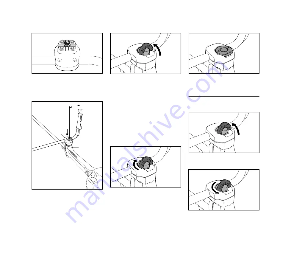
Use the spring (9) from the parts kit
supplied with the machine.
N
Place the spring (9) in the lower
clamp molding (10).
N
Position the clamp moldings (1) with
handlebar (2) on the handle
support (11).
N
Raise the grip of the wing screw (7)
to the upright position.
N
Turn the wing screw
counterclockwise as far as stop.
N
Push the wing screw into the handle
support as far as stop and then
screw it down – but do not finally
tighten yet.
N
Adjust the handlebar (2) so that
distance A is no more than 15 cm.
N
Line up the handlebar at a right
angle to the drive tube.
N
Turn the wing screw clockwise as
far as stop.
N
Fold the grip of the wing screw down
so that it is flush.
Adjusting the handlebar
Opening the wing screw
N
Raise the grip of the wing screw to
the upright position.
N
Turn the wing screw
counterclockwise until the handle
support can be moved.
4BA001 KN
9
10
11
1
4BA012 KN
2
A
2
4BA003 KN
7
4BA005 KN
4BA006 KN
4BA013 KN
4BA004 KN


