background image

0478 131 8349 A - EN

10

The STIHL robotic mower 
can be operated reliably 
and without interference 
in close vicinity to other 
robotic mowers. The wire 
signal meets the EGMF 
(European Garden 

Machinery Federation) standard with 
regard to electromagnetic emissions.

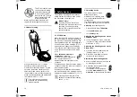
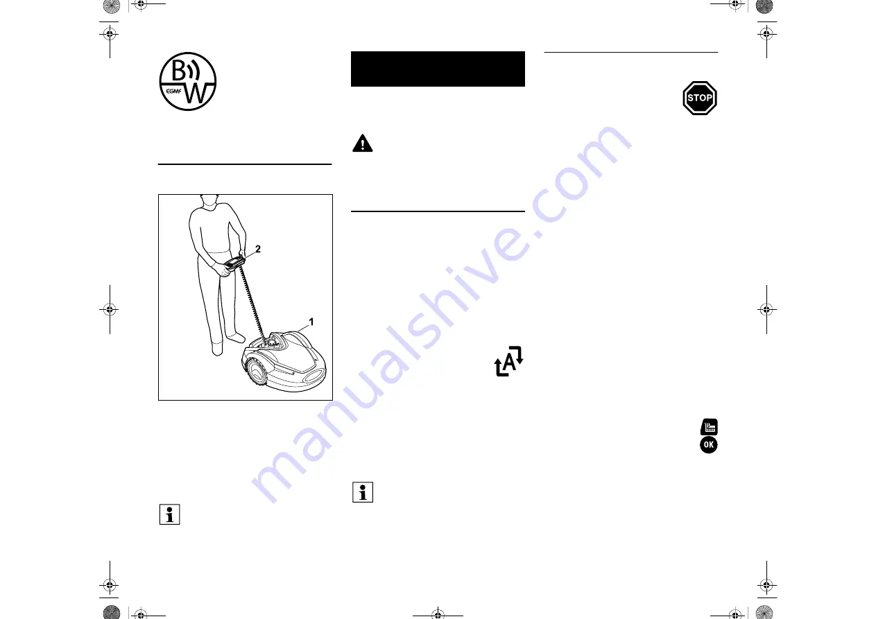
4.2 Manual mowing

With the robotic mower (1), it is also 
possible to mow the lawn as with a 
manually operated lawn mower. For this 
purpose, remove the control panel (2), 
select the "Hand control" option in the 
"Commands" menu, activate the mowing 
blade and self-propulsion and walk behind 
the robotic mower. (

Ö

15.6)

The machine is equipped with several 
safety devices for safe operation and for 
the prevention of improper use.

5.1 STOP button

When the red STOP button on the top of 
the robotic mower is pressed, operation of 
the machine is stopped immediately. The 
mowing blade comes to a standstill within 
a few seconds and the message "STOP 
button pressed" appears on the display. 
The robotic mower cannot be operated 
and is safe while the message is active. 
(

Ö

23.)

When 

automatic mowing is 

switched on

, following 

confirmation of the message with 
OK, the system enquires 
whether automatic operation is to be 
continued.
If the response is 

Yes

, the robotic mower 

continues to mow the lawn in accordance 
with the mowing plan.
If the response is 

No

, the robotic mower 

remains stationary in the mowing area and 
automatic mowing is switched off. (

Ö

11.5)

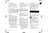
5.2 Disabling device

The robotic mower must be 
disabled prior to any 
maintenance or cleaning work, 
prior to transportation and prior 
to inspection.
The robotic mower cannot be operated 
when the disabling device is activated.

Activating

 the disabling device:

– Press and hold the 

STOP button

– in  the 

Commands

 menu

– in  the 

Safety

 menu.

Activating the disabling device via the 
Commands menu:

In the "Commands" menu, select the 
"Lock iMow" entry and confirm with the 
OK button. (

Ö

11.5)

Activating the disabling device via the 
Safety menu:

Open the "Safety" submenu in the 
"Settings" menu. (

Ö

11.16)

Select the "Lock iMow" entry and 
confirm with the OK button.

Deactivating the disabling device:

When required, wake up the machine 
by pressing any button.

Unlock the robotic mower using 
the illustrated button 
combination. For this purpose, 
press the 

Mow button

 and the 

OK button

 in the sequence illustrated.

The impact sensor and edge 
limitation are disabled during 
manual mowing.

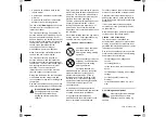
5. Safety devices

Risk of injury!

If a safety device is found to be 
defective, the machine must not be 
operated. Consult a specialist 
dealer; STIHL recommends STIHL 
specialist dealers.

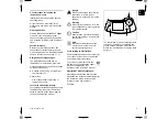
Pressing and holding the STOP 
button also activates the disabling 
device. (

Ö

5.2)

Summary of Contents for RMI 632

Page 1: ...STIHL RMI 632 RMI 632 P RMI 632 C RMI 632 PC Instruction manual EN RMI 632 0 RMI 632 0 C RMI 632 0 P RMI 632 0 PC A ...

Page 2: ...0478 131 8349 A I21 TIM 14089 001 2021 STIHL Tirol GmbH ...

Page 3: ...1 0478 131 8349 A 1 ...

Page 4: ...0478 131 8349 A 2 2 ...

Page 5: ...nsor 11 Lifting protection 11 Tilt sensor 11 Display illumination 11 Anti theft alarm 11 GPS protection 11 For your safety 11 General 11 Clothing and equipment 12 Warning dangers caused by electrical current 13 Battery 13 Transporting the machine 14 Before initial operation 14 Programming 15 During operation 15 Maintenance and repairs 16 Storage for prolonged periods without operation 17 Disposal ...

Page 6: ...perimeter wire 50 Wire clearances use iMow Ruler 50 Acute corners 51 Confined areas 51 Installing linking sections 52 No go areas 52 Secondary areas 53 Corridors 53 Guide loops for offset drive home 55 Accurate mowing along edges 56 Sloping terrain in the mowing area 56 Installing reserve wire 57 Using wire connectors 57 Docking station 58 Docking station controls 58 Notes on mowing 58 General 58 ...

Page 7: ...ied using the symbols described below in order to especially emphasise them in the instruction manual Texts relating to illustrations Some Illustrations which are necessary for use of the machine can be found at the front of this instruction manual The camera symbol serves to link the figures on the illustration pages with the corresponding text passages in the instruction manual Illustrations wit...

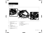
Page 8: ...ing contacts Connecting contacts to docking station 3 Rear wheel 4 Carrying handle Ö 5 6 5 Removable control panel Ö 3 3 Ö 15 2 6 Rotary handle for cutting height adjustment Ö 9 6 7 STOP button Ö 5 1 8 Front wheel 9 Mowing deck 10 Dual ground mowing blade Ö 16 3 11 Battery compartment 12 Carrier plate ...

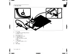
Page 9: ...tion 1 Floor plate 2 Cable guides for retaining the perim eter wire Ö 9 11 3 Power supply unit 4 Removable cover Ö 9 2 5 Charging contacts Connecting contacts to robotic mower 6 Control panel with button and LED Ö 13 1 7 Button 8 LED display ...

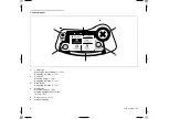
Page 10: ...robotic mower Ö 15 6 Navigating in menus Ö 11 1 2 OK button Manual mowing Ö 15 6 Navigating in menus Ö 11 1 3 Back button Navigating in menus Ö 11 1 4 Mow button Manual mowing Ö 15 6 Mowing independently of active times Ö 15 5 5 Rain sensor Ö 11 12 6 Graphical display ...

Page 11: ...ided must be separated from the remaining mowing area using the perimeter wire When automatic mowing is switched on the robotic mower independently leaves the docking station and mows the lawn during the active times Ö 11 7 The robotic mower automatically travels to the docking station to recharge the battery The number and duration of the mowing and charging operations within the active times are...

Page 12: ...mower continues to mow the lawn in accordance with the mowing plan If the response is No the robotic mower remains stationary in the mowing area and automatic mowing is switched off Ö 11 5 5 2 Disabling device The robotic mower must be disabled prior to any maintenance or cleaning work prior to transportation and prior to inspection The robotic mower cannot be operated when the disabling device is...

Page 13: ...ated an alarm signal sounds when the robotic mower is lifted unless the PIN code is entered within one minute Ö 11 16 The robotic mower can only be operated in conjunction with the docking station supplied A further docking station must be linked with the robotic mower Ö 11 16 5 10 GPS protection The models RMI 632 C RMI 632 PC are equipped with a GPS receiver When GPS protection is activated the ...

Page 14: ...or users Children must be kept away from the machine and mowing area during mowing operation Dogs and other pets must be kept away from the machine and mowing area during mowing operation For safety reasons any modification to the machine except the proper installation of accessories or attachments approved by STIHL is forbidden and results in voiding of the warranty cover Information regarding ap...

Page 15: ...e power supply unit and docking station must not be extended The power supply unit and cable must not be left on wet ground for prolonged periods Danger of electric shock Damaged cables connectors and plugs or electric cables which do not conform with regulations may not be used Always ensure that the power cables used are adequately protected by a fuse Detach electric cables at the plug and socke...

Page 16: ...t In particular short circuit protection must be ensured Transport the battery either in the original packaging or in the robotic mower 6 6 Before initial operation It must be ensured that all persons who use the machine are familiar with the instruction manual Carefully follow the instructions for installing the docking station Ö 9 1 and perimeter wire Ö 12 The perimeter wire and the power cable ...

Page 17: ...tors and programme the active times accordingly Ö 14 3 In particular programming must also be adapted so that no children spectators or animals are in the area to be mown during operation Changing the programming using the iMow app in the case of the RMI 632 C RMI 632 PC models can result in activities that will not be expected by other people Changes to the mowing plan must therefore be communica...

Page 18: ...keep your feet a safe distance from the blade To prevent the risk of injury due to slipping stumbling etc never run when mowing Be particularly careful when turning the robotic mower around or pulling it towards you backwards The risk of accidents is higher if the ground is damp due to increased danger of slipping Particular caution should be exercised during working in order to prevent slipping I...

Page 19: ...e and the user s requirements Genuine STIHL spare parts can be recognised by the STIHL spare parts number by the STIHL lettering and if present by the STIHL spare parts symbol On smaller parts only the symbol may be present Always keep warning and information stickers clean and readable Damaged or missing stickers must be replaced by new original plates from your STIHL specialist dealer If a compo...

Page 20: ... friendly manner Warning Read the instruction manual before initial use Warning Keep a safe distance from the machine during operation Keep other persons out of the danger area Warning Disable the machine before lifting it and before working on it Warning Do not climb onto or sit on the machine Warning Never touch the rotating blade Warning Keep children away from the machine and mowing area durin...

Page 21: ...cally conductive materials as well as old perimeter wire installations can interfere with the mower s operation It is recommended to remove these sources of interference Level and flat Preparatory measures Mow the lawn using a conventional lawn mower prior to initial installation ideal grass height 6 cm or less In the case of a hard and dry surface water the mowing area lightly in order to make it...

Page 22: ...ectly The areas around the docking station and outside of the perimeter wire must be flat and freely travellable Remove any bumps or depressions The corridor 2 is installed using the corridor template 3 Ö 12 11 Minimum clearance from the floor plate to the start of the corridor 50 cm Width of the free area to the side 44 cm Maximum clearance to the mowing area 12 m Installing the docking station o...

Page 23: ...move upwards Opening the panel Fold the panel 1 forwards Hold the panel in the opened position as the hinge springs will close it automatically The connections for the perimeter wire 1 and the power cable 2 are protected against the weather when the panel is closed Closing the panel Fold the panel 1 rearwards do not pinch any cables Fitting the cover ...

Page 24: ...imeter wire is not routed by the specialist dealer additional installation material not included in the standard equipment will be required to be able to operate the robotic mower Ö 18 The installation kits contain perimeter wire on a reel 1 as well as fixing pins 2 and wire connectors 3 The standard equipment in the installation kits may include additional parts not required for the installation ...

Page 25: ...t is available for installation of the robotic mower This program guides you through the entire initial installation process Setting the language date and time Installing the docking station Routing the perimeter wire Connecting the perimeter wire Linking the robotic mower and docking station Checking installation Set the cutting height to at least level 5 in the first weeks until the grass has gr...

Page 26: ...election with the OK button or select Change and repeat the language selection If necessary enter the 9 digit serial number of the robotic mower This number is printed on the identification plate sticker in compartment under control panel Set the current date using the control pad and confirm with the OK button An installation video is available at the www stihl com homepage Your STIHL specialist ...

Page 27: ...rder to avoid interference with the wire signal Connect the mains plug After completing this installation work press the OK button on the control panel Lift the robotic mower slightly by the carrying handle 1 to relieve the weight on the drive wheels Push the machine resting on its front wheels into the docking station Read the Notes on the docking station section Ö 9 1 and study the installation ...

Page 28: ...r wire starting at the docking station A distinction must be made between an internal docking station and an external docking station here Starting routing with an internal docking station Fasten the perimeter wire 1 to the ground on the left or right as appropriate next to the floor plate directly next to a wire outlet using a fixing pin 2 If the battery is discharged a plug symbol appears instea...

Page 29: ... wire end 1 with a length of approx 2 m Route the perimeter wire 2 in front of and behind the docking station 1 with 50 cm of clearance and at right angles to the floor plate A corridor can then be installed Ö 12 11 or the edge of the mowing area followed with the perimeter wire A freely travellable area with a minimum width of 44 cm must be available to the side of the floor plate 3 If offset dri...

Page 30: ...raping against the obstacle Route the perimeter wire 2 with the aid of the iMow Ruler 3 as illustrated If necessary extend the perimeter wire using the wire connectors supplied Ö 12 16 In the case of several adjacent mowing areas install secondary areas Ö 12 10 or join the mowing areas with corridors Ö 12 11 Last fixing pin with internal docking station Drive in the last fixing pin 1 on the left o...

Page 31: ...ing area behind the docking station 2 as illustrated then press the OK button Disconnect the power supply unit plug from the mains then press the OK button Remove the cover Ö 9 2 Then press the OK button on the control panel If the battery is not sufficiently charged to work through the remaining steps of the installation assistant an appropriate message is displayed In this case leave the robotic...

Page 32: ...r wire with external docking station Route the perimeter wire 1 in the area 2 under the floor plate To do this guide the wire into the wire outlets 3 4 loosen the pegs if necessary Insert the perimeter wire 1 into the cable guides in the floor plate and guide it through the socket 2 Connecting the perimeter wire Note Make sure that the contacts are clean not corroded dirty etc ...

Page 33: ... Ö 9 2 1 Fold open the left clamping lever 1 2 Insert the stripped wire end 2 into the terminal block as far as it will go 3 Close the clamping lever 1 Strip the right wire end 1 to the specified length X using a suitable tool and twist the wire strands X 10 12 mm 1 Fold open the right clamping lever 1 2 Insert the stripped wire end 2 into the terminal block as far as it will go 3 Close the clampi...

Page 34: ...is connected to the mains power supply the LED 1 illuminates Lift the robotic mower slightly by the carrying handle 1 and relieve the weight on the drive wheels Push the machine resting on its front wheels into the docking station Then press the OK button on the control panel 9 12 Linking the robotic mower and docking station Observe the Docking station controls section particularly if the LED doe...

Page 35: ...ot sufficiently twisted together Perimeter wire break Extraneous signals such as a mobile phone or the signal from another docking station Live underground cables reinforced concrete or disruptive metals in the ground under the docking station Maximum length of the perimeter wire exceeded Ö 12 1 Remedy Repeat linking without other corrective action Dock the robotic mower Ö 15 7 Connect the perimet...

Page 36: ...the mowing area with the front facing the perimeter wire Continuation following interruption After an interruption continue edge following with Yes No ends following of the perimeter wire and the next step of the installation assistant is called up The robotic mower docks after one complete circuit around the mowing area Then a second edge following run is started in the opposite direction Contact...

Page 37: ... be changed For this purpose select the required time interval using the control pad and open with OK Ö 11 7 If additional active times are required select the menu item New active time and open with OK Specify the start and end times of the new active time in the selection window and confirm with OK Up to three active times per day are possible If all the displayed active times are to be deleted ...

Page 38: ...stems in respective app stores Activation In order for the app and robotic mower to be able to exchange data the machine During the active times third parties must keep out of the danger area The active times should be adapted accordingly Moreover the applicable local regulations on the use of robotic mowers as well as the information in the For your safety Ö 6 section must be observed and the act...

Page 39: ... 1 serves for navigation in the menus Settings are confirmed and menus opened using the OK button 2 Menus can be exited again using the Back button 3 The main menu comprises 4 submenus displayed as buttons The selected submenu has a black background and is opened using the OK button In the second menu level the various submenus are shown as tabs The tabs can be selected by pressing the control pad...

Page 40: ...on is confirmed and the subordinate menu called up using the OK button 11 2 Status screen The status screen appears when standby mode of the robotic mower is ended by pressing a button when the Back button is pressed in the main menu during running operation There are two configurable fields in the top display area Various information regarding the robotic mower and the mowing operations can be di...

Page 41: ...odels Errors faults or recommendations are displayed together with warning symbol date time and message code If several messages are active they appear alternately Ö 23 11 3 Information area The following information is shown in the top right corner of the display 1 Charge state of the battery or charging in progress 2 Automatic mowing status 3 Time 4 Mobile radio signal RMI 632 C RMI 632 PC 1 Cha...

Page 42: ...us Lawn status Radio module status RMI 632 C RMI 632 PC 4 Settings Ö 11 10 iMow Installation Safety Service Dealer area 11 5 Commands Select the required command using the control pad and execute by pressing OK 1 Main menu 2 Lock iMow 3 Switch on automatic mowing Switch off automatic mowing 4 Drive to docking station 5 Manual mowing 6 Start mowing 7 Start time delayed mowing 8 Skip next active tim...

Page 43: ...ring the next active time Active times which have been cancelled in this manner are greyed out in the mowing plan They can be released for mowing again in the Active times menu Ö 11 7 If the command is performed several times in succession the next active time is always skipped If no active times remain for the current week the message No mowing will take place next week appears 9 Edge mowing Foll...

Page 44: ... and Active time on respectively The time window can be changed with Change active time If the selected active time is no longer required the menu item Delete active time should be selected 11 8 Mowing duration The weekly mowing time can be set under Adapt mowing duration The set value is adapted to the size of the mowing area Ö 9 14 Follow the instructions in the Adapting the programming section ...

Page 45: ...wn Mowing area in square metres This value is entered during initial installation or new installation Ö 9 7 Round time Duration of one circuit around the mowing area in minutes and seconds Starting points 1 4 Distance of the relevant starting point from the docking station in metres measured in a clockwise direction Ö 11 15 Circumference Circumference of the mowing area in metres Edge mowing Frequ...

Page 46: ...ormat Set the required date format 8 Track offset The robotic mower travels along the perimeter wire at a 6 cm offset from the wire as standard With this offset optimum docking is ensured The iMow Ruler is also designed for a track offset of 6 cm Only if necessary open the selection window with OK and set the required value 3 cm to 9 cm 9 Language Set the required display language The language sel...

Page 47: ... on and off When the passage is activated the robotic mower travels back home to the docking station offset at a distance along the perimeter wire Three versions can be selected Off Default setting The robotic mower travels along the perimeter wire Narrow 40 cm The robotic mower alternatively travels along the perimeter wire or offset by 40 cm Wide 40 80 cm The distance to the perimeter wire is se...

Page 48: ...the teach in procedure Manually following an interruption Automatically after docking The new starting points are saved following confirmation with OK Starting frequency The starting frequency defines how often a mowing operation is to begin from a starting point The default setting is 2 of 10 mowing operations 2 10 at each starting point Change the starting frequency as required after teach in If...

Page 49: ... lock PIN code query prior to resetting the machine to the factory defaults Time lock PIN code query for changing a setting if no PIN code has been entered for more than one month Setting protection PIN code query when settings are changed 3 GPS protection RMI 632 C RMI 632 PC For switching position monitoring on and off Ö 5 10 4 Change PIN code The 4 digit PIN code can be changed if required Firs...

Page 50: ...tic mower will then search for the wire signal and save it automatically This process takes several minutes Ö 9 12 11 17 Service 1 Blade change Installation of a new mowing blade is confirmed with OK 2 Find wire break If the red LED on the docking station flashes rapidly there is a break in the perimeter wire Ö 13 1 Find wire break Ö 16 7 3 Reset settings The robotic mower is reset to the factory ...

Page 51: ...between the perimeter wires of two mowing areas 12 2 Making a sketch of the mowing area During installation of the robotic mower and the docking station it is recommendable to make a sketch of the mowing area A page has been provided at the start of this Instruction Manual for this purpose The sketch should be modified in the event of subsequent changes Content of the sketch Contour of the mowing ...

Page 52: ... station cover and then connect the mains plug Check the wire signal Ö 9 12 Check docking Ö 15 7 If necessary correct the position of the perimeter wire in the area of the docking station 12 5 Wire clearances use iMow Ruler The perimeter wire 1 can be routed without clearance along obstacles that can be travelled on such as patios and paths The robotic mower then travels with one rear wheel outsid...

Page 53: ...ler 2 Wire clearance 33 cm Measuring the height of obstacles The robotic mower can cross adjoining areas such as paths if the height of the stepped area is less than 1 cm Height difference to obstacle that can be travelled on 1 is less than 1 cm route the perimeter wire 2 without clearance to the obstacle 12 6 Acute corners The perimeter wire is routed as illustrated in acutely angled lawn corners...

Page 54: ... close to one another Attach the linking section to the ground with a sufficient number of fixing pins 2 12 9 No go areas No go areas have to be installed around obstacles that the robotic mower must not touch around obstacles that are not sufficiently sturdy around obstacles that are too low Minimum height 10 cm STIHL recommends blocking off obstacles by means of no go areas or removing them chec...

Page 55: ...er because access is not possible In this manner several separate mowing areas can be surrounded with a single perimeter wire The robotic mower must be manually taken from one mowing area to another The mowing operation can be initiated via the commands Start mowing Ö 11 5 or Start time delayed mowing Ö 11 5 The docking station 1 is installed in the mowing area A which is cut fully automatically i...

Page 56: ...lied for installing the funnel shaped entrance and exit areas In corridors the lawn is only mown along the path of the perimeter wire If necessary activate automatic edge mowing or mow the corridor area manually on a regular basis Ö 11 5 Ö 11 14 If corridors are to be installed switch off offset drive home passage Ö 11 14 or install guide loops Ö 12 12 The specified wire clearances and the corrido...

Page 57: ...tivated guide loops must be provided if an external docking station has been installed or if there are corridors or confined areas in the mowing area Function When the robotic mower follows the perimeter wire offset at a distance it crosses one of these guide loops during the drive home It then travels to the perimeter wire and on to the docking station Guide loops with an external docking station...

Page 58: ...utomatically mow a slope in the mowing area up to 15 incline trouble free the perimeter wire must be installed in the slope with a minimum clearance to the edge of the incline A clearance of at least 100 cm must be observed for water features and sudden drops like edges and steps Slope with an incline of 5 15 If there is a slope with an incline of 5 15 in the mowing area the perimeter wire can be ...

Page 59: ...rve wire should be installed near difficult passages Route perimeter wire 1 as illustrated between 2 fixing pins spaced approx 1 m apart Attach the reserve wire to the ground in the centre using a further fixing pin 12 16 Using wire connectors In order to extend the perimeter wire or to connect loose wire ends only the gel filled wire connectors available as accessories may be used They prevent pr...

Page 60: ...ing Homecall Briefly press the button twice within 2 seconds during a mowing operation The robotic mower ends the running mowing operation searches for the perimeter wire and returns to the docking station to recharge the battery No further mowing operation takes place in the current active time 14 1 General The robotic mower is designed for the automatic mowing of lawns The grass is kept short th...

Page 61: ...re The coordinates are updated each time edge following is repeated When GPS protection is activated the owner of the machine is notified if the machine is operated outside the home area The PIN code is also requested on the robotic mower display 14 6 Manual mowing Do not activate the mowing blade or set the lowest cutting height in high grass The robotic mower load must never cause the mowing mot...

Page 62: ...mowing area during installation or during the creation of a new mowing plan The active times and the mowing duration can be changed individually the required mowing operations themselves are automatically distributed over the possible active times If required several mowing or charging operations can run during an active time If required the edge of the mowing area can be cut automatically at regu...

Page 63: ...r there Immediate mowing Call up the Start mowing command Ö 11 5 or press the Mow button The mowing operation starts immediately and continues until the selected time Time delayed mowing Call up the command Start time delayed mowing Ö 11 5 The mowing operation starts at the selected start time and continues until the selected end time RMI 632 C RMI 632 PC Start mowing using the app Ö 10 The mowing...

Page 64: ...g Ö 15 8 15 7 Docking the robotic mower Docking during automatic operation The robotic mower automatically travels to the docking station when the active time ends or when the battery is discharged Forcing docking If necessary insert the control panel Ö 15 2 If necessary switch on the docking station Ö 13 1 Activate the command Drive to docking station Ö 11 5 During a mowing operation Homecall can...

Page 65: ... the battery charge is too low the corresponding battery symbol appears In this case place the robotic mower in the docking station to recharge 16 1 Maintenance schedule The maintenance intervals are based on the operating hours among other factors The relevant Mowing hours counter can be called up in the Information menu Ö 11 9 The specified maintenance intervals must be strictly observed Mainten...

Page 66: ...so clean the mowing blade and the docking station Detach accumulated clipping deposits in the housing and in the mowing deck beforehand using a stick If necessary use a special cleaner e g STIHL special cleaner Regularly remove the carrier plate and remove grass residues Ö 16 6 16 3 Checking the mowing blade wear limits Activate the disabling device Ö 5 2 Tilt the robotic mower onto its side and l...

Page 67: ...r with the fastening nut Installing the mowing blade Clean the blade carrier plate and fastening nut prior to installation Fit the mowing blade 1 on the carrier plate 2 as illustrated Ensure the correct position of the retainers 3 in the mowing blade Screw on the fastening nut 1 as far as possible Several clicks are audible during tightening Ensure secure seating of the mowing blade by shaking car...

Page 68: ...ly clean the blade shaft 1 and the mounting on the carrier plate 2 Push the carrier plate as far as possible onto the blade shaft Install the mowing blade Ö 16 4 16 7 Finding a wire break The wire break search can be performed either with the control panel removed or inserted The control panel should be inserted for the fine search Before finding the wire break the button on the docking station mu...

Page 69: ...eft and right at the front of the robotic mower During the wire break search the signal strength is indicated on the display the wire sensors are in the ideal position above the perimeter wire when this value is at its highest The Wire signal OK symbol appears on the display when the wire sensors are correctly receiving the wire signal In the area of the wire break the signal strength drops and th...

Page 70: ...he mowing plan and change as necessary Ö 11 6 Switch on automatic mowing Ö 11 5 RMI 632 C RMI 632 PC If necessary activate Standard energy mode Ö 11 11 and switch on GPS protection Ö 5 10 16 9 Removing the docking station The docking station can also be removed if the robotic mower is to be stored for long periods e g winter break Preparing the robotic mower for storage for a long period Ö 16 8 Di...

Page 71: ...enance and care of the product group robotic mower battery powered STIHL RMI STIHL assumes no liability for material or personal damage caused by the non observance of information contained in the operating instructions in particular with regard to safety operation and maintenance or which arise through the use of unauthorised attachment or spare parts Please always observe the following important...

Page 72: ... packaging and accessories are all produced from recyclable materials and must be disposed of accordingly By disposing of materials separately and in an environmentally friendly manner valuable resources can be re used For this reason the machine should be disposed of for recycling at the end of its useful life Pay particular attention to the information in the Disposal section during disposal Ö 6...

Page 73: ...tting width 28 cm Speed of cutting utilities 3150 rpm Battery type Lithium ion Battery voltage UDC 29 V Cutting height 20 60 mm Protection class III Type of protection IPX4 In accordance with Directive 2006 42 EC and the EN 50636 2 107 standard Measured sound power level LWA 59 dB A Uncertainty KWA 3 dB A LWA KWA 62 dB A Sound pressure level LpA 48 dB A Uncertainty KpA 3 dB A Length 73 cm Width 54...

Page 74: ...in once the fault has been rectified In the case of errors awarded the priority High the text Contact your specialist dealer appears on the display The robotic mower can only be operated again once the fault has been rectified by a STIHL specialist dealer Message 0001 Data updated Press OK to release Possible cause The machine software has been updated Voltage loss Software or hardware error Remed...

Page 75: ...otic mower Ö 16 2 Level out any uneven areas holes depressions in the mowing area Message 0402 Drive motor fault Temperature range exceeded Possible cause Temperature in right drive motor too high Remedy Allow the robotic mower to cool down Message 0405 Drive motor fault Right wheel is stuck Possible cause Overload at right drive wheel Remedy Clean the robotic mower Ö 16 2 Level out any uneven are...

Page 76: ...Then press OK Possible cause Permanent collision detected Remedy Free the robotic mower remove the obstacle or change routing of perimeter wire if necessary then confirm the message with OK Check movement of the hood and confirm the message with OK Message 1125 Remove obstacle Check wire routing Possible cause Perimeter wire routed inaccurately Remedy Check the routing of the perimeter wire check ...

Page 77: ...ible cause The docking station was not found The start or end of a corridor was installed incorrectly Remedy Check the LED on the docking station switch on the docking station if necessary Ö 13 1 Check docking Ö 15 7 Check funnel shaped entrance and exit areas of the corridor Ö 12 11 Message 1190 Docking error Docking station occupied Possible cause Docking station occupied by a second robotic mow...

Page 78: ...Message 2032 Battery temperature Outside temperature range Possible cause Temperature in battery during charging too low or too high Remedy Allow the robotic mower to warm up or cool down observe permissible temperature range of battery Message 2040 Battery temperature Outside temperature range Possible cause Temperature in battery when starting mowing operation too low or too high Remedy Allow th...

Page 79: ...that the desired zone and perimeter wire overlap Ö 10 Message 2077 Desired zone Desired zone outside home area Possible cause The desired zone is outside the stored home area Remedy Redefine the desired zone Ö 10 Message 2090 Radio module Contact your specialist dealer Possible cause Communication with the radio module interrupted Remedy No action required firmware will be automatically updated if...

Page 80: ...programme sequence Power failure during automatic operation Robotic mower is located outside the mowing area Remedy Confirm message with OK Check power supply to the docking station the red LED must be illuminated permanently during operation then press the OK button Ö 13 1 Return the robotic mower to the mowing area then press the OK button Message 4005 Internal fault see message 4004 Message 400...

Page 81: ...asts Fault The robotic mower fails to mow after the commands Start mowing or Start time delayed mowing have been called up Possible cause Insufficient battery charge Rain detected Control panel not correctly inserted Message active Homecall activated on the docking station Remedy Charge the battery Ö 15 8 Set the rain sensor Ö 11 12 Insert the control panel Ö 15 2 Rectify displayed fault and confi...

Page 82: ...tion of the docking station Ö 9 1 Replace the charging contacts Fault Docking not working Possible cause Uneven entry area to docking station Dirty drive wheels or dirty floor plate Perimeter wire incorrectly routed in area of docking station Ends of perimeter wire not cut Remedy Level out the entry area to the docking station Ö 9 1 Clean the drive wheels and the floor plate of the docking station...

Page 83: ...off Perimeter wire routed inaccurately Grass is out of reach of mowing blade Remedy Mow the edge once or twice per week Ö 11 5 Check the routing of the perimeter wire Ö 11 14 check the clearances with the iMow Ruler Ö 12 5 Cut the unmown areas regularly using a suitable grass trimmer Fault No wire signal Possible cause Docking station switched off no LED illuminates Docking station not connected t...

Page 84: ...tion The robotic mower is not associated with the correct e mail address Remedy The radio module is switched off during linking then it is reactivated and the robotic mower can be reached again Activate the robotic mower by pressing the button set Standard energy mode Ö 11 11 Connect the machine on which the app is installed to the Internet Correct the e mail address Ö 10 25 1 Handover confirmatio...

Page 85: ...er wire 2 is routed around the pool B Wire clearances Ö 12 5 Clearance to the edge 33 cm Clearance to adjoining area that can be travelled on e g footpath with a stepped area height of less than 1 cm 0 cm Clearance around the tree 33 cm Clearance to the pond 100 cm Programming No further adaptation is necessary following definition of the size of the mowing area Points to note Unmown areas around ...

Page 86: ...ia a linking section Wire clearances Ö 12 5 Clearance to the edge 33 cm Clearance to adjoining area that can be travelled on e g footpath with a stepped area height of less than 1 cm 0 cm Clearance around the trees 33 cm Programming No further adaptation is necessary following definition of the size of the mowing area Points to note Tree in the corner of the mowing area mow the area behind the blo...

Page 87: ... e g footpath with a stepped area height of less than 1 cm 0 cm Around the tree 33 cm Clearance to the pond 100 cm Corridor Installation of a corridor 3 Wire clearance 27 cm Ö 12 11 Guide loops Installation of two guide loops 4 for using the offset drive home function Ö 11 14 Minimum clearance from the corridor entrance 2 m Note the minimum clearance to corners Ö 12 12 Programming Define the total...

Page 88: ...tacles 33 cm Clearance to the tree 33 cm Minimum wire clearance in the confined areas behind the vegetable patch 54 cm Secondary area Installation of a secondary area C linking section 3 on the patio accommodated in a cable duct Programming Define the size of the mowing area without secondary area program one starting point 4 in the confined area for using the offset drive home function Ö 11 14 st...

Page 89: ...unction Ö 11 14 Minimum distance from the corridor entrance 2 m Note the minimum clearance to corners Ö 12 12 Programming Define the size of the mowing area and program at least one starting point outside the corridor to the docking station Ö 11 15 Points to note Installation of a corridor 4 with funnel shaped entrance area 3 Ö 12 11 Wire clearance 27 cm The corridor 4 leads to the external dockin...

Page 90: ...0478 131 8349 A STIHL RMI 632 RMI 632 P RMI 632 C RMI 632 PC A ...

Reviews: