background image

Spare parts list

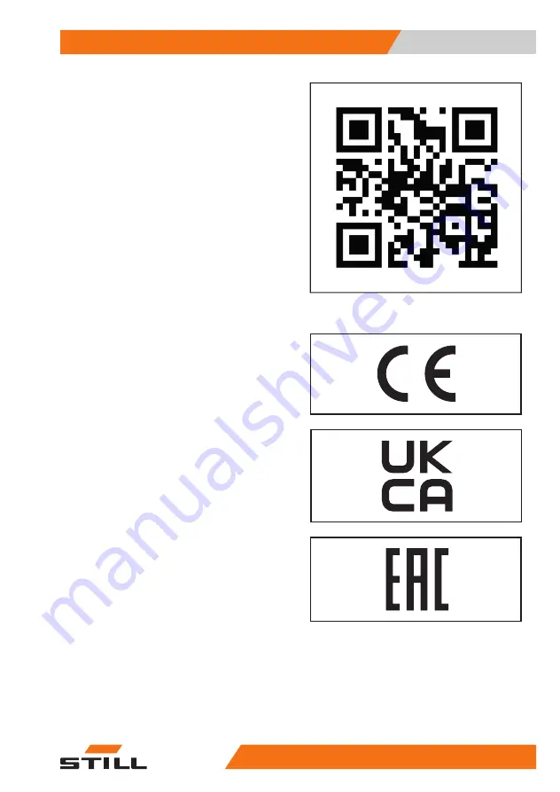
You can request to download the spare parts

list by copying and pasting the address https://

sparepartlist.still.eu into a web browser or by

scanning the QR code shown to the side.
On the web page, enter the following pass-

word: Spareparts24!
On the next screen, enter your email address

and truck serial number to receive an email

with the link and download the spare parts list.

Conformity marking

The manufacturer uses the conformity mark-

ing to document the conformity of the industri-

al truck with the relevant directives at the time

of placing on the market:

CE: in the European Union (EU)

UKCA: in the United Kingdom (UK)

EAC: in the Eurasian Economic Union

The conformity marking is applied to the

nameplate. A declaration of conformity is is-

sued for the EU and UK markets.
An unauthorised structural change or addition

to the industrial truck can compromise safety,

thus invalidating the declaration of conformity.

2511

conformity symbols

Introduction

1

Spare parts list

 5

45728043478 EN - 11/2021  -  09

Summary of Contents for EXV 10

Page 1: ...Pallet stacker EXV 10 Basic EXV 10 10i EXV 12 12i EXV 14C 14iC Original instructions 45728043478 EN 11 2021 09 ...

Page 2: ......

Page 3: ...cks Information on how to select suitable indus trial trucks for a particular area of applica tion Prerequisites for the safe operation of in dustrial trucks Information on the use of industrial trucks Information on transport initial commission ing and storage of industrial trucks Internet address and QR code The information can be accessed at any time by pasting the address https m still de vdma...

Page 4: ......

Page 5: ...f manufacturer and contact details STILL GmbH Berzeliusstraße 10 22113 Hamburg Germany Tel 49 0 40 7339 0 Fax 49 0 40 7339 1622 Email info still de Website http www still de Preface III 45728043478 EN 11 2021 09 ...

Page 6: ......

Page 7: ...ifications to Forklift 10 Applied equipment 10 User obligations 10 Environmental considerations 11 Disposal of components and batteries 11 Packaging 12 2 Safety Safety guidelines 14 General Precautions 14 General Safety Rules 14 Flooring requirements 14 Battery connection cables 15 Requirements for the traction battery charging area 15 Safety Regulations Relative to Forklift Use 15 Safety guidelin...

Page 8: ...itions 36 Tiller controls 38 OptiSpeed tiller if present 40 Types of lifting masts 41 Definition of directions 43 Markings 44 Location of labels 44 Serial number 45 Nominal value designation plate 46 Capacity plate 47 Chassis frame labelling 48 Options and variants 49 List of optional fittings 49 Numeric keypad Start up using a PIN option 50 Battery electrolyte level indicator LED optional 52 4 Us...

Page 9: ...iving 68 Before driving 69 Starting the truck 70 Check the information on the combined indicator 71 Behaviour in emergencies 72 Selecting the driving mode 72 Drive 73 Using the truck with the Tiller always active Creep Speed function optional 74 Reversing the direction of travel 76 Truck brake systems 77 Parking and stopping the truck 79 Forklift Use in Cold Storage Rooms 80 Lifting 81 Lift contro...

Page 10: ...lans 105 Fuses 107 Replacing the battery from above for trucks with 1000 kg and 1200 kg capacity 108 Replacing the battery from above for trucks with 1400 kg capacity 110 Battery replacement for version with side removal 111 Decommissioning 113 General Information 113 Forklift Towing 114 Temporary Putting Out of Commission 114 Checks and Inspections After a Long Period of Inactivity 114 Permanent ...

Page 11: ...1 Introduction ...

Page 12: ...tely trained operators only For the necessary operator training contact the authorised sales network Persons working near the forklift must also be instructed in the risks associated with use of the forklift In the interests of clear information some il lustrations in this manual show the forklift without the safety equipment guards pan els etc The forklift may not be used with out safety equipmen...

Page 13: ...lure to observe the instructions highlighted with this symbol may cause environmental damage NOTE This symbol is used to provide additional infor mation Introduction 1 How to Consult the Manual 3 45728043478 EN 11 2021 09 ...

Page 14: ...it has been delivered with the following documentation Original instructions Declaration of conformity If the truck has been delivered with a traction battery and or a battery charger ensure that these products conform to the order and that the corresponding operating and maintenance manuals are included as well as the declara tion of conformity for the battery charger If there is applied equipmen...

Page 15: ...arking The manufacturer uses the conformity mark ing to document the conformity of the industri al truck with the relevant directives at the time of placing on the market CE in the European Union EU UKCA in the United Kingdom UK EAC in the Eurasian Economic Union The conformity marking is applied to the nameplate A declaration of conformity is is sued for the EU and UK markets An unauthorised stru...

Page 16: ...H 1 For the markets of the European Union the EU candidate countries the EFTA States and Switzerland 2 For the United Kingdom market The declaration of conformity document is supplied with the industrial truck The declara tion shown explains the conformity with the provisions of the EC Machinery Directive and the Supply of Machinery Safety Regulation 2008 2008 No 1597 An unauthorised structural ch...

Page 17: ...handed over to the new owner if the industrial truck is sold on Introduction 1 Declaration that reflects the content of the declaration of conformity 7 45728043478 EN 11 2021 09 ...

Page 18: ...d centre approximately on the forklift s median longi tudinal plane DANGER The forklift must not be used for other purposes Any other use renders the user solely responsible for injury damage to persons and or objects and voids the warranty The following scenarios are examples of incor rect use of the forklift truck Transport on uneven irregular or non com pact surfaces loads that exceed the weigh...

Page 19: ...der extreme conditions extreme weather cold storage rooms presence of strong magnetic fields etc appropriate equipment and or us age precautions are necessary Contact the authorised sales network for information DANGER The truck must not be used in environments where there is a risk of explosion and the truck must not be used to handle explosive loads Trucks that must operate in environments where...

Page 20: ...e compatibility of such devices must be verified with the presence of operators us ing medical devices such as heart pacemakers Applied equipment To apply additional equipment after purchas ing you must contact the sales network au thorised by the truck manufacturer which will verify feasibility install the equipment add a label with the new residual capacity provide documentation on the equipment...

Page 21: ...of they must be disposed of treated or recycled in accordance with regional and national regulations NOTE The documentation provided by the battery manufacturer must be observed when dispos ing of batteries ENVIRONMENT NOTE We recommend working with a waste man agement company for disposal purposes Introduction 1 Environmental considerations 11 45728043478 EN 11 2021 09 ...

Page 22: ...ovide protection during trans port This packaging must be removed com pletely prior to initial start up ENVIRONMENT NOTE The packaging material must be disposed of properly after delivery of the truck Introduction 1 Environmental considerations 12 45728043478 EN 11 2021 09 ...

Page 23: ...2 Safety ...

Page 24: ... using just one fork Place the load on the fork carriage or in such a way that the centre of gravity of the load is as close as possible to the fork car riage The load must be placed on the fork arms so that the centre of gravity falls lengthwise on the mid point between the fork arms Do not drive with loads off centre laterally with respect to the forklift s median axis Lack of compliance with th...

Page 25: ...ed in or der to dilute or eliminate the gases produced in compliance with current national regula tions Safety Regulations Relative to Forklift Use The operator must familiarize himself with the forklift to be able to better describe any defects and assist maintenance personnel The operator trained and authorized to use the forklift must be familiar with the controls and performances of the forkli...

Page 26: ...ollution laws Oils Avoid contact with skin Do not inhale oil vapours Wear appropriate personal protective equip ment during truck maintenance operations gloves goggles etc to prevent the oil from coming into contact with your skin ENVIRONMENT NOTE The used oils and relative filters contain sub stances that are hazardous to the environment and they must be disposed of according to current regulatio...

Page 27: ... The replacement and disposal of the life expired battery must be carried out as required by law We advise you to contact the authorised service network that is equipped for eco friendly disposal in accordance with current regulations Safety 2 Safety guidelines 17 45728043478 EN 11 2021 09 ...

Page 28: ...f the truck must be instructed regarding the risks that arise through use of the truck In addition we draw your attention to the Safety Guidelines in these operating instructions Risks can include Escape of consumables due to leakages rupture of lines and containers etc Risk of accidents when driving on ramps or in conditions of poor visibility etc Falling tripping etc when moving the truck especi...

Page 29: ...rojecting to the side e g side shift turning and driving diagonally across slopes driving on slopes with the load pointing downhill oversized loads swinging loads steps or ramp edges WARNING These risks are caused by improper use Improper use e g swinging loads transporting liq uids etc is PROHIBITED unless specifically ap proved in writing by the manufacturer Electromagnetic radiation The limit v...

Page 30: ... LpAZ 70 dB A Uncertainty factor KpA 4 dB A The value is determined in a test cycle in ac cordance with Harmonised European Stand ard EN 12053 and declared according to EN ISO 4871 with weighted time percentages of the Transport Lifting and Idling modes CAUTION The value expressed above can be used to compare forklift trucks of the same category This cannot be used to determine the noise level in ...

Page 31: ... in this case CAUTION The value expressed above can be used to compare forklift trucks of the same category It cannot be used to determine the operator s daily exposure to vibra tions during real operation of the truck these vibra tions depend on the conditions of use floor condi tions method of use etc and therefore daily expo sure must be calculated using data from the place of use Safety 2 Vibr...

Page 32: ...two in spections have been carried out The inspection date is indicated by an adhe sive label on the truck Arrange for the service centre to perform periodic safety inspections on the truck Observe guidelines for checks carried out on the truck in accordance with FEM 4 004 The operator is responsible for ensuring any defects are remedied without delay Contact your service centre NOTE Observe the n...

Page 33: ...rgency stop button OptiSpeed tiller Protective guard 1 2 3 4 5 6 Horn Electromagnetic brake Truck braking when the tiller arm reaches the upper end position and lower end posi tion Automatic speed reduction with forks raised approximately 500 mm above the ground only available on 1400 kg version 7 8 9 10 NOTE These devices must be checked daily as de scribed in Chapter 4 Safety 2 Safety devices 23...

Page 34: ... be used until they have been properly repaired Do not remove or deactivate safety devices and switches Fixed set values may only be changed with the approval of the manufacturer Work on the electrical system e g connecting a radio additional headlights etc is only per mitted with the manufacturer s written appro val All electrical system interventions must be documented Safety 2 Safety devices 24...

Page 35: ...3 Overview ...

Page 36: ...lly laden Raising Nominal load EXV10 Basic and EXV10 1000 kg EXV12 and EXV12 i 1200 kg EXV14C and EXV14iC 1400 kg Pump unit EXV10 Basic power 2 2 kW EXV10 power 1 5 kW EXV12 EXV12 i EXV14C EXV14iC power 3 2 kW Different types of lift mast Simplex mast E non telescopic with central cylinder Telescoping mast TE two stage tele scoping mast without free lift and two lateral cylinders NiHo mast two sta...

Page 37: ...unter current by switching the drive direc tion counter current controlled by the anti crush safety button Electromagnetic safety controlled by the emergency stop handle safety electromagnetic controlled by the re lease of the tiller safety electromagnetic controlled when the tiller arm reaches the lower end position Electromagnetic parking applied when power supply is cut off On board equipment T...

Page 38: ...ator button Fuse carrier Battery connector Built in battery charger if present Pump motor Hydraulic oil reservoir 1 2 3 4 5 6 7 8 9 10 Stabiliser wheel Traction wheel Gearbox Traction motor Brake Forks Load wheels Electronic panel Battery Lift cylinder 11 12 13 14 15 16 17 18 19 20 Overview 3 Overviews 28 45728043478 EN 11 2021 09 ...

Page 39: ...ngular position of the throttle Releasing the throttle causes the truck to brake and then come to a standstill Fork lowering button 4 Press the button 4 to lower the fork arms Fork movement can be stopped at any time by releasing the button 4 The forks will stop in the position reached NOTE The speed of the forks is proportional to how hard the button 4 is pressed except for the version BASIC When...

Page 40: ...uck will be re versed if the button 7 comes into contact with the body of the operator When the oper ator moves away and releases the button 7 the truck stops Creep Speed button 8 optional The button 8 is fitted with the tiller always active option Creep Speed Keeping the button 8 pressed while turn ing the throttle 2 3 activates creep speed regardless of the tiller position Keeping the button 8 p...

Page 41: ... stop in the position reached The straddle lifting button 9 is active only when the tiller is angled to the working posi tion Straddle lowering button 10 Press the button 10 to lower the straddles when the button is released the straddles will stop in the position reached The straddle lowering button 10 is active only when the tiller is angled to the working position Overview 3 Instruments and con...

Page 42: ...on until the next service Constant service date overdue 3 Red indicator light Indicator light illuminated indicates an error or alarm 4 Green indicator light Switched off truck switched off Switched on truck switched on 5 Malfunction code The combined indicator may display an er ror code When an error code is displayed please call our service department Make a note of these error codes before swit...

Page 43: ...rious types of problem Do not operate the truck 9 Temperature alarm red Cool down the truck If the problem persists contact the technical service centre Tortoise LED and pictogram illumina ted as soon as tortoise mode is selected Overview 3 Instruments and controls 33 45728043478 EN 11 2021 09 ...

Page 44: ...ect the truck drive mode from the two available modes Tortoise or Hare turn the switch key to the desired position To switch off the truck turn the key to the 0 position Version with Digicode optional On the optional version with Digicode start the truck by following the procedure descri bed in the relevant paragraph Digicode op tion Then turn the selector to the desired position depending on the ...

Page 45: ...e causes of the emergency then re lease the tiller in the rest position and un lock the emergency stop handle by lifting it DANGER This button must be used only in emergencies the repeated use of this device may cause problems with the electronic equipment or breakdowns 0252_003 047 1 Overview 3 Instruments and controls 35 45728043478 EN 11 2021 09 ...

Page 46: ... forks using the appropri ate button In this position the operator can raise or lower the straddles for versions with strad dle initial lift only Position 2 braking position In this position the drive is locked and the parking brake is engaged NOTE In this position lifting and lowering of the forks and straddles if fitted is blocked NOTE When the tiller is released it automatically re turns to pos...

Page 47: ...p speed position This function is activated by pressing the creep speed button on the tiller 3 and ro tating the drive control throttle 4 or by pressing the creep speed button and the fork lifting button The truck travels at limi ted speed OM2283 3 4 4 Overview 3 Instruments and controls 37 45728043478 EN 11 2021 09 ...

Page 48: ...osition of the throttle Releasing the throttle causes the truck to brake and then come to a standstill Fork lowering button 4 Press the button 4 to lower the fork arms Fork movement can be stopped at any time by releasing the button 4 The forks will stop in the position reached NOTE The speed of the forks is proportional to how hard the button 4 is pressed except for the version BASIC When the for...

Page 49: ...e truck will be re versed if the button 7 comes into contact with the body of the operator When the oper ator moves away and releases the button 7 the truck stops Creep Speed button 8 optional The button 8 is fitted with the tiller always active option Creep Speed Keeping the button 8 pressed while turn ing the throttle 2 3 activates creep speed regardless of the tiller position Keeping the button...

Page 50: ...ly when the tiller is angled to the working position OptiSpeed tiller if present The different work zones of the tiller depend ing on the tilt are explained below In zone 1 the brake is applied and the truck cannot be moved In zone 2 the maximum authorised speed varies according to the tilt of the tiller The reference 5 represents the curve of the speed inside zone 2 In zone 3 the truck can reach ...

Page 51: ...the lifting speed of the fork carriage is twice that of the internal mast CAUTION In locations with a low ceiling be aware that the load height may be greater than the mast height NiHo When the lift button is pressed the fork car riage is raised to the top of the internal mast h2 by the central cylinder then the lateral cylinders raise the internal mast up to the maximum height h3 NOTE During lift...

Page 52: ... Triplex The function is identical to that of the NiHo mast but has a greater lift height with the same mast height CAUTION In locations with a low ceiling be aware that the load height may be greater than the mast height h3 h2 0252_003 100 V2 Overview 3 Types of lifting masts 42 45728043478 EN 11 2021 09 ...

Page 53: ...tions Direction of movement defined by the regula tions Forward travel 1 preferred direction of travel Right 2 Reverse travel 3 Left 4 0252_003 008 4 2 3 1 Overview 3 Definition of directions 43 45728043478 EN 11 2021 09 ...

Page 54: ...danger label only on version with straddle initial lift function i Operating and maintenance manual label 1 2 3 4 5 6 7 Version set up for gel batteries On board battery charger label Annual testing label Germany only Warning label Danger of crushing feet label only on ver sion with straddle initial lift function i Cold store label on cold store version on ly 8 9 10 11 12 13 Overview 3 Markings 44...

Page 55: ...and maintenance man ual for the on board battery charger 8 This symbol where present indicates that the truck is set up for the gel battery version Do not use other types of battery 9 This label is present only on the version with the on board battery charger The label highlights the possibility of choosing the charging curve 10 This label is present only on trucks sold in Germany The label indica...

Page 56: ... Kingdom the designation plate will read Air craft ground support equipment instead of Industrial truck Manufacturer Production number Year of manufacture Unladen weight without battery in kg Maximum battery weight in kg Minimum battery weight in kg Additional weight ballast in kg QR code For more detailed information please refer to the technical data in the operating man ual In this zone there m...

Page 57: ...d on the capacity plate refer to compact and homogeneous loads and must not be exceeded otherwise the stability of the truck and the load bearing capacity of the structures may be compromised DANGER Risk of accident when forks are changed If the forks are changed and a different type of forks to the original forks is fitted the residual load capaci ty changes When forks are changed a new residual ...

Page 58: ...he truck s serial number is marked on the chassis frame The serial number is located in the following places A for standard versions of the truck B for models with initial lift capability Overview 3 Markings 48 45728043478 EN 11 2021 09 ...

Page 59: ...nager Built in rectifier LED battery electrolyte level indicator Lift lock at predefined heights unlockable via appropriate confirmation button only for 1400 kg version Truck speed limited automatically with load at h3 1500 mm only for 1400 kg version Battery removal roller unit only for 1400 kg version CAUTION Contact the technical service network authorised by the manufacturer for information on...

Page 60: ...ing THE ADMINIS TRATOR CODE IS IMPORTANT FOR ALL DIGI CODE SET TINGS 0 0 0 0 0 0 0 0 by default continuous red con tinuous green 3 Once the diodes have been switched off the electronic key automati cally reverts to operat ing mode New operator code 0 4 5 6 7 8 red off green flash ing 2 code accepted Example of a new oper ator code 45678 Allocating opera tor codes 2 5 4 3 2 1 red off green flash in...

Page 61: ... value accepted Example automatically switches off after 1 min 60 s if not used Minimum setting 10 s maximum 3000 s Deactivating the automatic switch off 2 0 red off green flash ing 2 command ac cepted Stand by NOTE The stand by function is only available with the Digicode option To prolong battery life the truck can be put in to energy saving mode when it is not in use After a certain period of d...

Page 62: ... the distilled water in the battery Operation If the LED 1 or 2 is green there is a suf ficient level of electrolyte in the battery The battery must not be topped up with distilled water If the LED 1 or 2 is red there is an insuf ficient level of electrolyte in the battery The battery must be topped up with distilled wa ter 1 2256 2 Overview 3 Options and variants 52 45728043478 EN 11 2021 09 ...

Page 63: ...4 Use ...

Page 64: ...e will enable him to put in place any necessary additional safety measures Safety instructions relating to use of the truck Behaviour when driving The operator must obey the same rules within the plant as on the road The operator must drive at a speed appropriate for the driving conditions For example the operator should drive slowly around corners when entering and travelling through narrow passa...

Page 65: ... warn them well in advance Stop working with the truck imme diately if the people do not leave the danger area despite the warnings DANGER Risk of injury There is a risk of physical injury in side the danger area Danger of death from falling loads Do not stand on the forks Standing or walking under the forks is strictly forbid den even when they are not loaded Danger area The danger area is the ar...

Page 66: ...e technical characteristics Regulations regarding the traffic routes and the manoeuvring areas Only traffic routes authorised by the operator or his agent may be used Traffic routes must be free of obstacles Loads may only be un loaded and stored in places designed for this purpose The operator or his agent must en sure that no unauthorised person approaches the working area Hazards Hazards on the...

Page 67: ...eans during transport using appropriate restraint systems Block the wheels with wedges to prevent even the slightest move ment Transport Disconnect the battery connector Chocking the truck Secure the truck against rolling and sliding with chocks 1 Lashing down the truck Attach the lashing ropes 2 to the mast OM0747 0252_003 010 1 1 2 Climatic Conditions for Transport and Storage The forklift must ...

Page 68: ...k and the rope sling must be suffi cient to bear the weight of the truck with its battery The position is indicated by a hook symbol DANGER Use a crane with a suitable lifting capacity for the weight of the truck which is indicated on its data plate Also take into account the weight of the bat tery fitted if applicable referring to the relevant identification plate Lifting operations must be per f...

Page 69: ...Breaking In This type of forklift does not require special breaking in operations Use 4 Breaking In 59 45728043478 EN 11 2021 09 ...

Page 70: ...ve very slowly during the operational tests Ensure that the truck is in good working condi tion prior to start up These checks supple ment and do not replace the scheduled main tenance operations Check the area under the forklift truck for leaking consumables Check the condition of the forks 5 and oth er load carrying equipment to ensure they show no noticeable damage e g bends cracks significant ...

Page 71: ...tle s on the tiller are working correctly Make sure that the buttons and throttle au tomatically return to their correct position af ter release Check that the battery plug outlet are cor rectly positioned and intact Make sure that the start stop key works cor rectly Check that the truck brakes and stops when the throttle is released Check that the truck brakes and stops when the tiller is release...

Page 72: ...curred and the truck was not fitted with an anti crush device The truck automatically shifts into reverse when the anti crush device on the tiller head comes into contact with the driver s body When the operator moves away from the anti crush device the vehicle stops even if for ward travel is selected again Normal operation may be resumed after re leasing the throttles Checking the anti crush saf...

Page 73: ...ger powered Releasing the tiller in driving area B sends the tiller into the area C and cuts traction Checking the emergency stop Drive slowly forwards Press emergency stop button 1 The truck stops Pull the emergency stop button 1 The truck is functional NOTE Ensure the stabilising wheels are correctly ad justed This influences braking effectiveness 0252_003 029 5 A B C 0252_003 047 1 Use 4 Checks...

Page 74: ...Checking the horn Operate the horn switch 1 The horn sounds 0203_003 012 1 Use 4 Checks and operations prior to use 64 45728043478 EN 11 2021 09 ...

Page 75: ...ean Parliament and of the Council states that the employer shall take the measures necessary to ensure that the work equipment made available to workers in the undertaking or establishment is suitable for the work to be carried out or properly adapted for that pur pose and may be used by workers without im pairment to their safety or health In selecting the work equipment which he proposes to use ...

Page 76: ...nd lifting con trols located on the helm head DANGER All other positions should be considered incorrect and dangerous DANGER Sitting on the truck is strictly prohibited DANGER Risk of feet being crushed Ensure that your feet are sufficiently far away from the truck chassis Recommended position for pick up and de posit of the load OM2278 Use 4 Operator position 66 45728043478 EN 11 2021 09 ...

Page 77: ... Recommended position when in gear pref erential gear Use 4 Operator position 67 45728043478 EN 11 2021 09 ...

Page 78: ...ility Driving the truck while seated is prohibited During operation in pedestrian mode Never sit on the truck to drive it The truck must not be used as a stepladder The truck was not designed to transport people and must not be used for this pur pose The operator must always stay within the truck clearance Stay in the safety area working area de fined by the manufacturer Use of a telephone or radi...

Page 79: ... on the forks DANGER Danger of death from falling loads Climbing on or walking under the forks is strictly prohibited even when they are not loaded Hazard area The hazard area is the area in which people are in danger from the movement of the forklift truck its work equipment and its lifting devices e g accessories or load The hazard area al so includes areas in which a load could fall or in which...

Page 80: ...operator or his representa tive must ensure that no unauthorised person accesses the working area Hazards Hazards on traffic routes must be signalled by means of road signs or possibly by additional warning notices Starting the truck Carry out all of the daily checks to be per formed by the operator Pull the emergency shutdown handle Put the tiller in the vertical position To start the truck turn ...

Page 81: ...hen the battery is fully charged the 10 sta tus bars are lighted As battery capacity falls the display moves to the left If the battery is 80 discharged two status bars are lit The lifting function is switched off The battery must be recharged Hourmeter The hour meter 4 indicates the number of operating hours of the machine The display is activated as soon as the ma chine is switched on The green ...

Page 82: ... by pulling on it CAUTION This safety device must only be used in an emergen cy Selecting the driving mode NOTE The truck has two driving modes Turn the switch key 1 to the desired posi tion Tortoise position gentle acceleration and deceleration max speed 4 km h Hare position strong acceleration and decel eration max speed 6 km h 0252_003 047 1 0252_003 051 1 Use 4 Driving 72 45728043478 EN 11 202...

Page 83: ...uipped with the OptiSpeed option see Querverweisfeh ler Ziel mit ID Fahren_Option nicht gefun den NOTE One of the travel throttles 2 or 3 on the tiller can be operated with the right or left hand Al ways operate the travel throttle slowly as the truck responds instantly Abrupt starting or braking or reversing the direction of travel should be avoided at all costs Forward travel Use your thumb to p...

Page 84: ...he forks to be lifted with the tiller in any posi tion Unlike the standard version by follow ing the instructions below the truck functions travel and lifting lowering of forks are also active with the tiller in the vertical position To enable truck lifting with the tiller in the verti cal position Press and hold the button 3 Then press the fork lifting button Release the button 3 to disable this ...

Page 85: ... the activation sequence is accidentally re versed i e with the tiller in the vertical posi tion the throttle 4 is turned first and then the button 3 is pressed The truck will move in creep speed as ex pected in the direction of the forks Travel in the direction of the operator is not enabled Use 4 Driving 75 45728043478 EN 11 2021 09 ...

Page 86: ...t to move again in the opposite direction Reverse direction with a load on the forks To reverse direction with a load on the forks put the drive control throttle in the neutral position and wait for the truck to stop Then turn the drive control throttle in the op posite direction of travel to the previous one CAUTION The operator must regulate the travel control by adapting truck braking to the ty...

Page 87: ...eyond the neutral position in the opposite direction to the direction of travel When driving the truck turn the travel con trol beyond the neutral position in the oppo site direction to the truck s direction of trav el The truck will decelerate more forcefully but will come to a gradual stop When the truck stops zero speed put the travel con trol in the neutral position Caution If you do not put t...

Page 88: ...ase the tiller The tiller will automatically return to the upper end posi tion The truck will decelerate very sharply to a stop WARNING The condition of the floor surface considerably af fects the braking distance of the truck The operator must consider this factor while driving Parking brake When the traction control throttle is re leased the truck stops using the electro magnetic brake when its ...

Page 89: ...he ground Turn off the truck using the start stop key If the Digicode option is fitted turn off the truck by pressing the button for two sec onds Press the emergency stop button DANGER Park the truck in such a way that it does not ob struct passageways and or render unusable emer gency equipment e g fire extinguishers and fire hydrants Use 4 Driving 79 45728043478 EN 11 2021 09 ...

Page 90: ...nd parked outside the cold area cold storage room CAUTION If the truck has been working in environments at tem peratures below 5 C and it is taken outside the cold storage room let it stand either for a sufficiently long time to allow any condensation to evaporate at least 30 minutes or a sufficiently short time to prevent the formation of any condensation less than 10 mi nutes Avoid the formation...

Page 91: ...to touch or stand on moving parts e g lifting device pushing devices work in stallations load lifting devices Fork lifting Press the button 4 The forks will be lifted up to the maximum height Fork movement can be stopped at any time by releasing the push button Fork arms lowering Press the button 3 The fork descends to the lowest position Fork movement can be stopped at any time by re leasing the ...

Page 92: ...ng the truck to operate on uneven surfaces or slopes WARNING Risk of crushing feet Keep your feet clear of the straddles To lift the straddles press the button 2 To lower the straddles press the button 1 0203_003 025 2 1 0248_003 033 Use 4 Lifting 82 45728043478 EN 11 2021 09 ...

Page 93: ...ty changes When forks are changed a new residual capacity plate must be affixed If a truck is supplied without forks the residual ca pacity plate for standard forks is affixed see chapter 6 Technical Data DANGER Wear protective footwear Always keep a suitable distance between your feet and the truck Risk of crushing feet when manoeuvring the truck CAUTION The transport of persons or passengers is ...

Page 94: ...ruck s area of operation CAUTION Do not touch nearby loads or loads beside or in front of the load being handled Arrange loads with a small space between them to prevent them coming into contact with one another DANGER Never leave the truck with the forks raised whether loaded or not WARNING When lifting the load pay attention to the dimensions of the column and the load Do not strike the ceiling ...

Page 95: ...Permissible lift height 2600 mm 2 WARNING The illustrations are only examples Only the values stated on your truck s plate should be taken into consideration WARNING If small items are being transported or if the load ex ceeds the height of the fork carriage a load protec tive guard must be installed to prevent the items from falling on the operator Picking up the load Load pick up from the ground...

Page 96: ...to the part of the forks protruding from the load to be lifted Do not strike the wall the shelving or other loads and or objects behind the load to be picked up Lift the load a few centimetres from the ground and read the Transporting loads section Load pick up from shelving Approach the shelving at moderate speed Use the drive control throttles to gradually slow down and stop the truck perpendicu...

Page 97: ...oad centre of gravity must be centred between the forks DANGER Pay attention to the part of the forks protruding from the load to be lifted Do not strike the wall the shelving or other loads and or objects behind the load to be picked up Raise the load a few centimetres until it is resting fully on the forks If the load is stable and secure on the forks proceed with the following steps In the even...

Page 98: ...perator and drive very slowly and carefully in a straight line away from the shelves Brake gradually Check that there is sufficient space be tween the forks and the shelving Lower the load to the transport position ap proximately 300 mm from the ground and read the Transporting loads section Use 4 Moving the load 88 45728043478 EN 11 2021 09 ...

Page 99: ... s view a second person on foot must assist with manoeuvres in order to warn the driver of any obstacles In this case driving is only authorised at walking speed and with the greatest care Stop the truck immediately if you lose contact with the person accompanying you DANGER Lower or raise the load until there is sufficient ground clearance approximately 300 mm Never transport loads with forks rai...

Page 100: ...DANGER Danger of load tipping over Avoid sudden starts and stops Approach corners slowly and carefully Use 4 Moving the load 90 45728043478 EN 11 2021 09 ...

Page 101: ... the driving position Look be hind to check that the way is clear Turn the throttle in the direction of travel towards the operator and drive very slowly and carefully in a straight line away from the shelves Brake gradually Check that there is sufficient space be tween the forks and the shelving Lower the forks to the ground Depositing a load on the ground Approach the load deposit area Lower the...

Page 102: ...gonally WARNING When travelling on a slope with a load on the forks the load on the forks must be facing uphill DANGER Risk of accident and falling Keep the truck at the required safety distance from the edges of uphill and downhill slopes CAUTION In certain cases driving with the forks pointing to wards the top of the slope is permitted even if the truck is not loaded In these cases drive with th...

Page 103: ... You must drive onto the loading bridge slowly and carefully The operator must check that the vehicle to be loa ded or unloaded is sufficiently secure so that it will not move and that it is suitable to support the stress created by the truck The lorry driver and the forklift operator must agree on the time of departure of the lorry Towing trailers The forklift is not qualified to tow trailers Use...

Page 104: ... service department NOTE Four error codes may be displayed For exam ple E1 239 E2 212 E3 426 E4 320 Make a note of these error codes before switching off the truck These error codes are stored but are not necessarily displayed on the combined indicator 0 0 h 0252_003 065 V2 Use 4 Fault displays 94 45728043478 EN 11 2021 09 ...

Page 105: ...onnect the battery plug 2 Closing WARNING Risk of crushing Be sure not to leave anything between the battery cover and the edge of the chassis when closing the cover Connect the battery plug Close the battery cover 0252_003 075 2 0252_003 088 V2 2 Use 4 Charging the battery 95 45728043478 EN 11 2021 09 ...

Page 106: ...f the battery open the battery hood and hold the hood open Connect the battery outlet to the battery charger to begin charging Turn on the external battery charger After the battery charging operation is com pleted switch off the battery charger Unplug the battery charger Plug the battery in again Close the battery hood NOTE Refer to the battery operating instructions for more information Charging...

Page 107: ...and cause dangerous situations As regards safety precautions follow the instructions given in the bat tery manual and those included in the Safety Guidelines of this manual DANGER If the truck is fitted with an on board battery charg er it is strictly prohibited to connect the battery to an external battery charger CAUTION Make sure that the mains supply voltage complies with the battery charger s...

Page 108: ...rved Fire prevention measures WARNING Do not smoke or use a naked flame when handling batteries In the area des ignated for parking the truck to recharge the battery or battery charger there should be no flammable materials or substances that can cause sparks within a radius of at least 2 metres The charg ing area must be well ventilated Keep a fire extinguisher at hand Safe parking Park the truck...

Page 109: ...cid must be neutralised immediately Terminals and soldering lugs must be clean and lightly greased with pole grease Using the truck with extension leads DANGER Use of the truck with extensions is only permitted with a maximum extension length of 3 m Use 4 Charging the battery 99 45728043478 EN 11 2021 09 ...

Page 110: ...Use 4 Charging the battery 100 45728043478 EN 11 2021 09 ...

Page 111: ...5 Maintenance ...

Page 112: ... be per formed by the service network authorised by the manufacturer in order to keep the machine in per fect condition and compliant with technical specifi cations NOTE Contact the authorised service network for a maintenance contract appropriate to your fork lift CAUTION Maintenance intervals are defined for standard use In the following cases it is necessary to reduce the interval between the v...

Page 113: ...uck on a flat surface and make sure that it cannot move accidentally Fully lower the forks Switch off the truck DANGER Before performing any intervention on the electrical system disconnect the battery outlet from the rela tive plug Maintenance 5 Preliminary maintenance operations 103 45728043478 EN 11 2021 09 ...

Page 114: ...l be reduced For chain lubricant specifications see the section Supply table in chapter 6 Alterna tively contact the sales network authorised by the manufacturer Using a clean brush spread a thin layer of lubricant along the entire length of the chain Lubricate the chain both inside and outside This will help the lubricant to pene trate the links of the chain If dirt has accumulated on the chain t...

Page 115: ...ease the rods and levers Check the bushes and levers Steering wheels Steering visually inspect the mounting of the tiller Steering unit bearing grease if there is a lubrication nipple Wheels Wheels and rollers check for any damage foreign matter or signs of wear Wheels check that they are at the correct tightness Rollers check that they are correctly mounted Brake Electromagnetic brake check for s...

Page 116: ...sliding tracks of the mast profiles Mast check that it is correctly mounted Lift cylinders chains rollers and end stops check the condition mounting and operation Lifting chain check chain adjustment and maintenance clean adjust grease Fork holder check that the fork holder is in good condition is correctly mounted and is operating correctly Protective device check that the anti shearing protectiv...

Page 117: ...danger Before carrying out any work on the electrical in stallation the battery 2 must be disconnected Remove the two screws 2 0252_003 088 V2 2 0252_003 105 2 2 4 3 Maintenance 5 Maintenance plans 107 45728043478 EN 11 2021 09 ...

Page 118: ...the preliminary operations for maintenance park the truck on a flat surface switch off the truck and then press the emergency off button Remove the battery hood open the battery hood turn the clasp upwards 3 until it rea ches the B position and then remove the hood by sliding it off sideways 2341 A B 3 Disconnect the socket from the battery male connector Maintenance 5 Maintenance plans 108 457280...

Page 119: ...e battery 6 see the user manual of the lift ing device Insert the safety hooks of the sling into the appropriate battery slots The entire sling must be suitably sized accord ing to the weight of the battery 5 6 1044_606 004 Lift the battery using a hoist that is suitably sized for the weight of the battery Keep a sufficient safety distance between the bat tery and the truck to avoid damage to the ...

Page 120: ...ngs Make sure that the lifting capacity of the slings is suitable for the weight of the battery The rope slings must be pulled vertically To prevent short cir cuits it is recommended that batteries with polar terminals or unprotected con nections be covered with a rubber mat Attach the lifting device 5 correctly to the battery 6 see the user manual of the lift ing device Insert the safety hooks of...

Page 121: ...tery compartment Open the latch of the battery retainer to un lock it DANGER Risk of crushing hands The battery must be re moved by a single operator only The operator must follow the operating instructions given in this section positioning himself on the same side as the battery side removal roller unit Pull the battery outwards sliding it along the rollers on the truck frame and position ing it ...

Page 122: ...which type of battery to use check the battery characteristics provided in the TECHNICAL DATA chapter CAUTION Before using the truck check that the latch is closed correctly as it acts as a battery retainer and must hold the battery in place CAUTION When closing the battery cover take care to position the cables of the battery plug correctly so as not to damage them Maintenance 5 Maintenance plans...

Page 123: ...ssioning General Information The operations to be performed for Tempora ry decommissioning and Permanent de commissioning are listed in this chapter Maintenance 5 Decommissioning 113 45728043478 EN 11 2021 09 ...

Page 124: ...e a month Raise the forklift so that the wheels do not touch the ground otherwise the wheels will become flat at the point of contact with the floor Cover the forklift with a NON plastic sheet Checks and Inspections After a Long Period of Inactivity DANGER Perform the following operations before using the forklift Clean forklift truck thoroughly Check the battery charge level and reas semble it in...

Page 125: ...lift according to local legislation ENVIRONMENT NOTE In particular batteries fluids oils fuels lubri cants etc electrical and electronic compo nents and rubber components must be dis posed of in compliance with specific local leg islation for each type of material DANGER Disassembly of the forklift for scrapping is extreme ly hazardous Maintenance 5 Decommissioning 115 45728043478 EN 11 2021 09 ...

Page 126: ...Maintenance 5 Decommissioning 116 45728043478 EN 11 2021 09 ...

Page 127: ...6 Technical data ...

Page 128: ...Overall dimensions Technical data 6 Overall dimensions 118 45728043478 EN 11 2021 09 ...

Page 129: ...2 1 9 Wheelbase y mm 1157 WEIGHTS EXV 10 Ba sic EXV 10 Simplex Telescopic NiHo 2 1 Tare weight with battery kg 708 5 788 6 2 2 Load per laden axle drive side load side kg 617 1091 654 1134 2 3 Load per unladen axle drive side load side kg 518 190 572 216 WHEELS EXV 10 Ba sic EXV 10 Simplex Telescopic NiHo 3 1 Tyres Solid rubber Polyurethane 3 2 Drive wheel sizes Øxl mm Ø230 x 75 3 3 Wheel sizes lo...

Page 130: ...le 4 3 Free lift h2 mm see mast table 4 4 Lift h3 mm see mast table 4 5 Height with mast removed h4 mm see mast table 4 9 Height of tiller in driving posi tion min max h14 mm 740 1230 4 15 Height of forks when lowered h13 mm 86 4 19 Overall length unladen l1 mm 1768 1788 4 20 Length including shoulder of forks l2 mm 618 2 638 2 4 21 Total width b1 mm 800 4 22 Fork dimensions s e l mm 65 180 1150 2...

Page 131: ...l speed km h 6 0 6 0 5 2 Lifting speed laden unladen m s 0 12 0 16 0 11 0 23 0 11 0 2 5 3 Lowering speed laden unla den m s 0 23 0 23 0 3 0 28 0 31 0 25 5 7 Max surmountable gradient KB 5 with without load 5 10 5 9 Acceleration time with with out load over 10 metres s 8 7 5 10 Service brake Electromagnetic ELECTRIC MOTOR EXV 10 Ba sic EXV 10 Simplex Telescopic NiHo 6 1 Traction motor performance K...

Page 132: ...and Ni Ho and I2 44 mm 35 mm The version with forks s 60 mm is the only version inten ded for gauge b5 680 mm only with forks I 1000 mm and for Triplex columns 3 Straddles lowered 4 Straddles raised 5 Weight and constraint on the axles for con figurations with Simplex column h1 2390 mm 6 Weight and constraint on the axles for con figurations with Telescopic column h1 1940 mm 7 Weight and constrain...

Page 133: ... 1912 2024 2424 2924 3324 3824 4224 h4 2502 2902 3402 3802 4302 4702 h1 initial lift h1 standard 6 mm NiHo EXV 10 h1 1490 1690 1940 2140 2390 2590 h1 h2 1012 1212 1462 1662 1912 2112 h2 h3 2024 2424 2924 3324 3824 4224 h4 2502 2902 3402 3802 4302 4702 h1 initial lift h1 standard 6 mm Technical data 6 Datasheet VDI EXV 10 Basic and EXV 10 123 45728043478 EN 11 2021 09 ...

Page 134: ...iplex 2 1 Tare weight with battery kg 788 6 935 7 2 2 Load per laden axle drive side load side kg 671 1317 690 1445 2 3 Load per unladen axle drive side load side kg 572 216 651 284 WHEELS EXV 12 Telescopic NiHo Triplex 3 1 Tyres Polyurethane 3 2 Drive wheel sizes Øxl mm Ø230x75 3 3 Wheel sizes load side Øxl mm 1xØ85x100 3 4 Stabiliser wheels sizes Øxl mm Ø140x54 3 5 Number of wheels drive side lo...

Page 135: ...0 180 1150 4 24 Frontal width b3 mm 534 710 4 25 Outside fork spread b5 mm 520 560 680 560 4 32 Ground clearance at the middle of the distance between forks m2 mm 30 4 33 Working aisle with pallet 1000 x 1200 b12 x I6 fork insertion 1200 Ast3 mm 2294 2321 4 34 Working aisle with pallet 800 x 1200 b12 x I6 fork insertion 800 Ast3 mm 2265 2310 4 35 Turning radius Wa mm 1420 PERFORMANCE EXV 12 Telesc...

Page 136: ... kg 195 6 6 Energy consumption according to VDI cycle kW h 1 OTHER EXV 12 Telescopic NiHo Triplex 8 1 Type of drive control AC Control 8 4 Noise level at driver s ears 2 5 dB dB A 65 EXV 12 i 1 CHARACTERISTICS EXV 12 i Telescopic NiHo Triplex 1 3 Drive electric diesel petrol LPG Electric 1 4 Drive type manual pedestrian ride on standing ride on seated order picking Pedestrian 1 5 Capacity Load Q k...

Page 137: ...Number of wheels drive side load side x drive wheel 1x 1 2 3 6 Drive side track width b10 mm 518 3 7 Load side track width b11 mm 380 DIMENSIONS EXV 12 i Telescopic NiHo Triplex 4 2 Height with lift mast retracted h1 mm see mast table 4 3 Free lift h2 mm see mast table 4 4 Lift h3 mm see mast table 4 5 Height with mast removed h4 mm see mast table 4 6 Initial lift h5 mm 130 4 9 Height of tiller in...

Page 138: ...3 2392 4 2452 3 2437 4 4 35 Turning radius Wa mm 1629 3 1558 4 PERFORMANCE EXV 12 i Telescopic NiHo Triplex 5 1 Travel speed km h 6 0 6 0 5 2 Lifting speed laden unladen m s 0 15 0 3 0 15 0 26 5 3 Lowering speed laden unladen m s 0 4 0 3 0 29 0 31 5 7 Max surmountable gradient KB 5 with without load 7 15 5 9 Acceleration time with without load over 10 metres s 8 4 7 5 5 10 Operating brake electrom...

Page 139: ...sion with forks s 60 mm is the only version inten ded for gauge b5 680 mm only with forks I 1000 mm and for Triplex columns 3 Straddles lowered 4 Straddles raised 5 Weight and constraint on the axles for con figurations with Simplex column h1 2390 mm 6 Weight and constraint on the axles for con figurations with Telescopic column h1 1940 mm 7 Weight and constraint on the axles for con figurations w...

Page 140: ... 3324 3824 4224 3636 4386 h4 2502 2902 3402 3802 4302 4702 4118 4868 h1 initial lift h1 standard 6 mm Datasheet VDI EXV 14C and EXV 14iC EXV 14C CHARACTERISTICS EXV 14C Telescopic NiHo Triplex 1 3 Power unit electric diesel petrol LPG Electric 1 4 Drive type manual pedestrian stand on seated order picker Pedestrian 1 5 Load capacity Q kg 1400 1 6 Load centre c mm 600 1 8 Load distance centre of dr...

Page 141: ...es Øxl mm Ø140 x 54 3 5 Wheels number drive side load side x drive wheel 1x 1 2 3 6 Track width drive side b10 mm 518 3 7 Track width load side b11 mm 380 DIMENSIONS EXV 14C Telescopic NiHo Triplex 4 2 Height of mast lowered h1 m m see mast table 4 3 Free lift h2 m m see mast table 4 4 Lift h3 m m see mast table 4 5 Height of mast extended h4 m m see mast table 4 9 Height of tiller arm in driving ...

Page 142: ...urning radius Wa mm 1573 10 PERFORMANCE EXV 14C Telescopic NiHo Triplex 5 1 Forward travel speed km h 6 0 6 0 5 1 1 Reverse travel speed km h 6 0 6 0 5 2 Lifting speed with without load m s 0 14 0 25 5 3 Lowering speed with without load m s 0 34 0 26 0 34 0 19 0 29 0 19 5 8 Climbing ability KB 5 with without load 5 10 5 9 Acceleration time with without load 10 metres s 8 7 5 10 Service brake elect...

Page 143: ...an stand on seated order picker Pedestrian 1 5 Load capacity Q kg 1400 1 6 Load centre c mm 600 1 8 Load distance centre of drive axle to fork x mm 721 1 641 2 697 1 617 2 1 9 Wheelbase y mm 1336 1 3 1256 2 3 1381 1 4 1301 2 4 WEIGHT EXV 14iC Telescopic NiHo Triplex 2 1 Service weight with battery kg 1048 7 1180 8 2 2 Axle load with load drive side load side kg 872 1576 1 925 1655 1 2 3 Axle load ...

Page 144: ...3 m m see mast table 4 5 Height of mast extended h4 m m see mast table 4 6 Initial lift h5 mm 130 4 9 Height of tiller arm in driving posi tion min max h14 mm 740 1230 4 10 Height of the load rollers h8 mm 80 4 15 Fork height lowered h13 mm 86 4 19 Overall length without load l1 mm 1940 3 9 1985 4 9 1964 3 9 2009 4 9 4 20 Length to fork face l2 mm 790 3 835 4 814 3 859 4 4 21 Total width b1 mm 800...

Page 145: ...ravel speed km h 6 0 6 0 5 1 1 Reverse travel speed km h 6 0 6 0 5 2 Lifting speed with without load m s 0 14 0 25 5 3 Lowering speed with without load m s 0 34 0 26 0 34 0 19 0 29 0 19 5 8 Climbing ability KB 5 with without load 7 15 5 9 Acceleration time with without load 10 metres s 8 7 5 10 Service brake electromagnetic TRANSMISSION EXV 14iC Telescopic NiHo Triplex 6 1 Traction motor rating KB...

Page 146: ...8 forks 1150 mm 9 With forks 1150 mm with forks 950 mm 200 mm 10 Acc to VDI 2198 2012 for trucks with or without fork initial lift with forks 1150 mm and with tiller arm in working position and fully rotated with tiller arm fully rotated anti clock wise 30 mm 11 Battery compartment 112 vertical remov al 12 Battery compartment 65 vertical removal 13 Battery compartment 68 vertical removal 14 Batter...

Page 147: ...sed mast height h1 566 mm with load backrest height from forks 1000 mm Mas t type NiHo Hei ght mas t low er ed h1 mm 141 5 166 5 191 5 211 5 236 5 256 5 h1 mm Fre e lift h2 mm 895 114 5 139 5 159 5 184 5 204 5 h2 mm Lift heig ht h3 mm 184 4 234 4 284 4 324 4 374 4 414 4 Hei ght mas h4 mm 236 4 286 4 336 4 376 4 426 4 466 4 Technical data 6 Datasheet VDI EXV 14C and EXV 14iC 137 45728043478 EN 11 2...

Page 148: ...ered h1 m m 1665 1915 2065 2265 h1 mm Free lift h2 m m 1145 1395 1545 1745 h2 mm Lift height h3 m m 3516 4266 4716 5316 Heigh t mast raised h4 mm 4036 4786 5236 5836 with increased mast height h1 566 mm with load backrest height from forks 1000 mm Technical data 6 Datasheet VDI EXV 14C and EXV 14iC 138 45728043478 EN 11 2021 09 ...

Page 149: ... design requirements for electric motors and variable speed drives All motors in this industrial truck are exempt from Regulation EU 2019 1781 because these motors do not meet the description giv en in Article 2 Scope Item 1 a and be cause of the provisions in Article 2 2 h Mo tors in cordless or battery operated equip ment and Article 2 2 o Motors designed specifically for the traction of electri...

Page 150: ...Technical data 6 Eco design requirements for electric motors and variable speed drives 140 45728043478 EN 11 2021 09 ...

Page 151: ...his manual 4 Declaration of conformity 6 Definition of directions 43 Discharge indicator 71 Disposal Battery 11 Components 11 Drive 73 Driving 68 Safety instructions 54 Driving safety instructions 68 E EC declaration of conformity in accordance with the Machinery Directive 6 Emergency stop handle 35 Ergonomic dimensions 65 Error codes 94 F Fault displays 94 H Hazard area 69 Hazards 70 I Intended u...

Page 152: ...echnical description 26 Braking system 27 Characteristics 26 Driving 27 On board equipment 27 Raising 26 Tests and actions prior to use 60 Transport 57 Transporting loads 89 Types of lifting masts 41 Triplex 42 Types of lift mast NiHo 41 Simplex 41 Telescopic 41 U Update of this manual 4 Use 0 V Visibility when driving 68 Index 142 45728043478 EN 11 2021 09 ...

Page 153: ......

Page 154: ...STILL GmbH 45728043478 EN 11 2021 09 ...

Reviews: