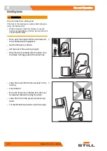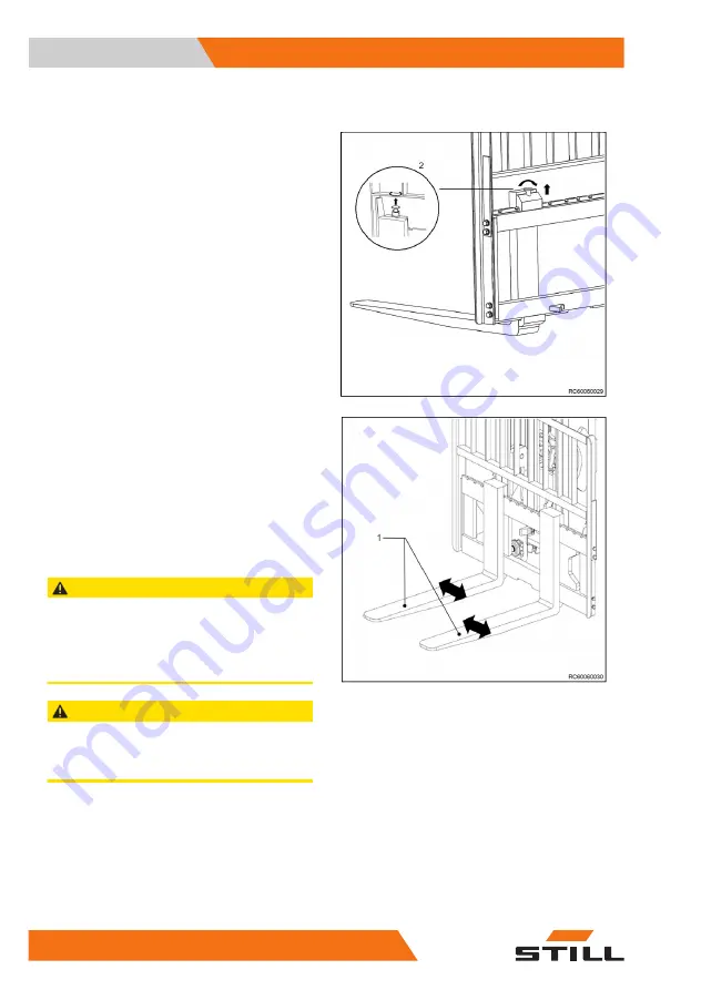
Adjusting the fork arm distance
–
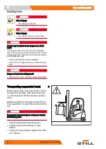
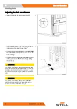
Raise the knob (2) and rotate it by 90°.
–
Adjust the fork arms (1) according to the di-
mensions of the load to be lifted.
–
Ensure that an equal distance is maintained
from both fork arms to the centre line of the
fork carriage.
–
Ensure that the fork arms are locked in one
of the grooves on the fork carriage using
the knob (2).
CAUTION
For greater load stability, the distance between the
two fork arms must be as large as possible while re-
maining consistent with the lifting points of the load,
so that the load centre of gravity is between the fork
arms.
CAUTION
For greater load stability, the position of the fork
arms must be as symmetrical as possible with re-
spect to the centre of the fork carriage.
Use and Operation
4
Handling loads
90
60048011601 EN - 08/2020
Summary of Contents for RCG15
Page 2: ......
Page 4: ......
Page 10: ......
Page 11: ...1 Introduction ...
Page 19: ...2 Safety ...
Page 41: ...3 Information about the truck ...
Page 52: ...Information about the truck 3 Location of the decals 42 60048011601 EN 08 2020 ...
Page 53: ...4 Use and Operation ...
Page 122: ...Use and Operation 4 Decommissioning 112 60048011601 EN 08 2020 ...
Page 123: ...5 Maintenance ...
Page 159: ...6 Technical datasheet ...
Page 160: ...Dimensions Technical datasheet 6 Dimensions 150 60048011601 EN 08 2020 ...
Page 168: ...Technical datasheet 6 Mast specifications 158 60048011601 EN 08 2020 ...
Page 172: ......
Page 173: ......
Page 174: ...STILL GmbH 60048011601 EN 08 2020 ...
Page 176: ......
Page 177: ...7 Diagrams ...
Page 179: ...Hydraulic diagram Diagrams 7 Hydraulic diagram 169 60048011601 EN 08 2020 ...
Page 180: ...Diagrams 7 Hydraulic diagram 170 60048011601 EN 08 2020 ...
Page 181: ......
Page 182: ...STILL GmbH 60048011601 EN 08 2020 ...


