–
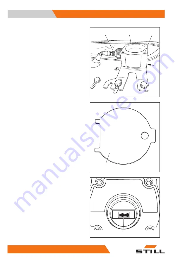
Turn the union nut (4) anti-clockwise to
loosen it. Disconnect the electrical connec-
tion assembly by pulling out the plug.
–
On the underside of the assembly base-
plate on the overhead guard, hold four nuts
(3) in place.
–
Unscrew four socket head screws (2).
The key (5) is secured with a nut under the as-
sembly baseplate.
–
Carefully remove the ceiling sensor (1).
The sensor is adjusted using DIP switches (6).
–
To access the DIP switches, open the cover
on the underside of the sensor housing with
the key (5).
During this process, the two tabs of the key (5)
fit into the recesses of the cover.
–
Using the DIP switches "1 to 5" (6), adjust
the range and the sensitivity of the sensor.
The DIP switches can be adjusted using a
small screwdriver.
Deckensensor_Anbau
1
4
2
3
5
Deckensensor_Einstellschlüssel_V2
1
2 3 4 5 6 7 8
6
DIP-Schalter_V2
Operating
4
Auxiliary equipment
232
56358042501 EN - - 11
Summary of Contents for RX60-60
Page 2: ......
Page 13: ...1 Foreword ...
Page 20: ...Overview Foreword 1 Your truck 8 56358042501 EN 11 ...
Page 41: ...2 Safety ...
Page 70: ...Safety 2 Emissions 58 56358042501 EN 11 ...
Page 71: ...3 Overviews ...
Page 83: ...4 Operating ...
Page 336: ...Operating 4 Decommissioning 324 56358042501 EN 11 ...
Page 337: ...5 Maintenance ...
Page 344: ...Maintenance 5 General maintenance information 332 56358042501 EN 11 ...
Page 381: ...6 1000 hour maintenance annual mainte nance ...
Page 385: ...7 Technical data ...
Page 398: ...Technical data 7 Fuse assignment 386 56358042501 EN 11 ...
Page 407: ......
Page 408: ...STILL GmbH 56358042501 EN 11 ...


