3
3
4
4
2
2
5
1
5
02
Steer axle
4
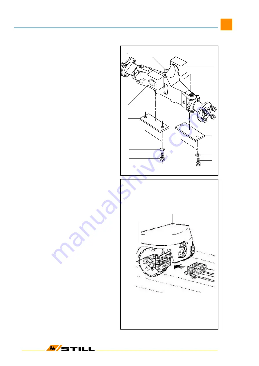
Configuration of steer axle
The articulating steer axle suspended from the
counterweight is mounted in 2 neoprene blocks. The
stub axles are supported in the axle beam on tapered
roller bearings. Steering is limited by stop screws on
the stub axles.
1
axle beam
2
fixing plates
3
hex. hd. bolt
4 spring washer
5
neoprene blocks
Steer axle removal
CAUTION: Remove steer axle only with mast in
position on the truck!
Risk of tipping!
- Apply the parking brake.
-Securely chock the front wheels to prevent
rolling of the truck.
- Slacken steer wheel nuts.
- Jack up rear of the truck at counterweight (x)
and place wooden blocks under the counter-
weight in front of the axle.
- Remove wheels.
- Disconnect the hydraulic connections at steer
cylinder.
C
AUTION:
Prepare for oil spillage when
disconnecting the hydraulic connections!
Catch oil in a pan of adequate capacity
and dispose of the used oil in accordance
with laws and regulations.
- Remove the 4 socket head screws which re-
tain the steer axle in place.
- Slide a hand pallet truck under the steer axle
with wooden blocks placed on the fork ends
of the hand pallet truck.
- Using a lever, drive steer axle out of roll pins
and lower the axle onto the hand pallet truck.
Steer axle installation
- Reverse the removal procedure.
- The slots of the roll pins must face the direc-
tion of forward travel.
-Torque the 4 socket heads to:
M
A
= 195 Nm
CAUTION: Do not swap hydraulic connec-
tions left and right!
Workshop Manual 7052/56/74-76, 7054/58/77-79
Summary of Contents for STEDS R70-16
Page 1: ......
Page 15: ...03 Workshop Manual 7052 56 7054 58 Technical Data for Maintenance Service 3 ...
Page 16: ......


