8
ASSEMBLY
Step Three
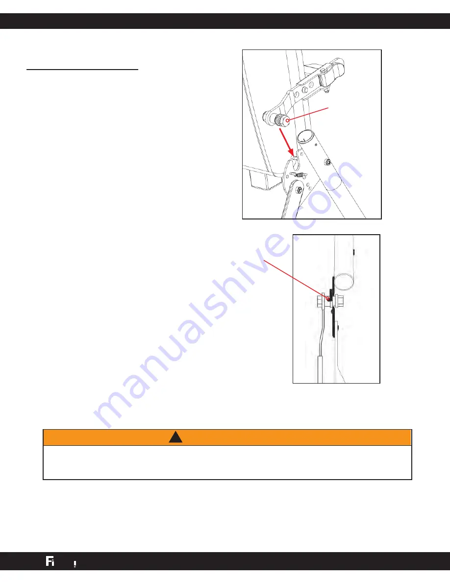
Attach the Table Bed Assembly
(FS-1030) to the A-frame
(FS-1010)
• Holding each side near the
Roller Hinges, pick up the Table
Bed and stand at the front of
the A-frame where the crossbar
is located. Lower each pivot pin
into the A-frame hinge plates at
the same time (Figure 6). Figure
7 shows the correct placement
of the pivot pin into the hinge
plate.
• Make sure that both pivot pins
are seated at the base of the
slot in the hinge plate. Check to
make sure that the self-locking
hooks have closed over both
pivot pins (Figure 7), and the
table rotates smoothly.
WARNING
!
Failure of the self-locking hooks to close over both pivot pins is indication of
improper assembly and if not corrected, could result in serious injury or death!
Figure 6
Figure 7
Self-locking
hook
pivot pin
9
ASSEMBLY
Step Four
Insert the Main Shaft
(FS-1050) into the Table Bed
Assembly (FS-1030)
• With the height adjustment
settings on the Main Shaft facing
up, slide the end of the Main Shaft
into the bushing in the Main Shaft
housing (Figure 9).
• Pull out the height selector locking
pin to allow the Main Shaft to
slide in further (Figure 10). For the
purpose of easy assembly, slide
in the Main Shaft and release the
pin in the last height setting (Refer
to the Owner’s Manual for proper
height adjustment before use).
• The Main Shaft must rest against
the crossbar of the A-frame
(Figure 11). The crossbar prevents
the table from rotating forward
when the user steps on the Foot
Platform. If the Main Shaft does
not rest on the Crossbar as shown
in Figure 11 then the Table Bed
has been assembled backwards
onto the A-frame and this must be
corrected before use.
Figure 9
Figure 10
Locking Pin
t p
S
ne
S Y S T E M
T M
t p
S
ne
S Y S T E M
T M
Figure 11
Crossbar


