3 | Product description
16
10/2019 | ID 443150_en.00
3.5.2
PKX, PHKX, KS mounting positions
STOBER coordinates the lubricant fill volume and structure of the gear unit types listed above to the mounting position of
the gear unit in the machine. The mounting position of a gear unit is determined upon ordering and specified in the order
documents.
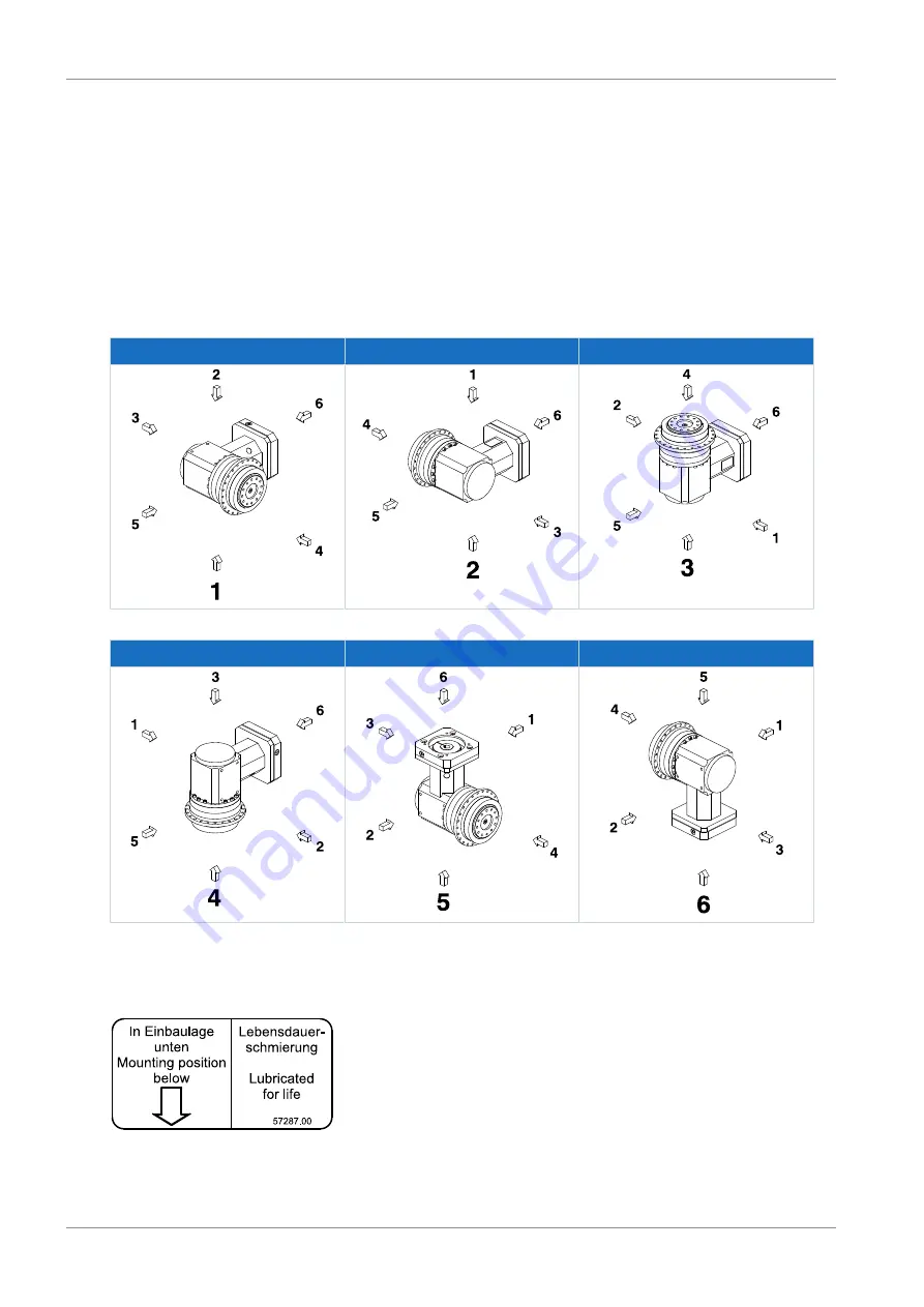
The standard mounting positions of the gear unit types listed above are illustrated in the images below, using the PHKX
gear unit type as an example. For the PKX gear unit type, the output shaft is implemented as a solid shaft, not a flange
shaft. For the KS gear unit type, the output shaft is either implemented as a solid shaft, flange hollow shaft or hollow shaft
with shrink ring on side 3.
The numbers identify the gear unit sides. The mounting position is defined by the gear side facing downwards.
EL1
EL2
EL3
EL4
EL5
EL6
An adhesive label is applied to the gear unit that explains the designated mounting position. The arrow on the adhesive
label indicates the side with which the gear unit must be mounted facing down.
Fig. 2: Adhesive label for the mounting position


