background image

Setup of POSITool

Operation manual

ID 442233.05

WE KEEP THINGS MOVING

17

5

5.3

Inverter view

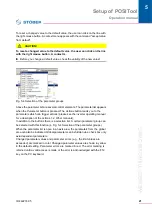
An inverter entry is identified by the resource name and the designation. They are 

entered in the configuration assistant.

The configuration assistant is called under "Projecting wizard." This can be used 

to change features such as number of axes or motor types at all times. The 

inverter entry has a separate path for each axis area and the global area. Each 

path contains a configuration and a parameter screen (except at the configuration 

level 0 - see chapter 6 Access level) and the available assistants.

To open a configuration screen, a parameter screen or an assistant, double-click 

the applicable entry. A configuration screen or a parameter screen is opened in 

the working area. An assistant is not dependent on the working area and switches 

other processing areas to inactive. The items Communication, Diagnosis and 

Commissioning are described in the next few chapters.

Fig. 5-2 Inverter entry

The 

File

 menu has several items for management of an inverter within a project:

Information

Please note that POSITool can communicate exclusively with an 

SDS 5000 if the inverter entry of the SDS 5000 is configured in an 

IGB entry or an EtherCAT entry. See chapter 5.4 IGB Entry or the 

EtherCAT documentation for more information (see chapter 1.2 

Other manuals).

Information

To maintain clear organization, a project should not contain more 

than 32 inverters. However, many more can be added.

Summary of Contents for POSIDRIVE FDS 5000 series

Page 1: ...POSIDRIVE FDS 5000 Projecting manual V 5 6 N or later 03 2015 en Installation Connecting Accessories PosiTool page 105 ...

Page 2: ...nded use 10 2 3 Risk assessment 10 2 4 Ambient conditions 11 2 5 Qualified personnel 11 2 6 Transportation and storage 12 2 7 Installation and connection 12 2 8 Commissioning operation and service 13 2 9 Disposal 13 2 10 Residual dangers 14 2 11 UL compliant use 14 2 12 Presentation of notes on safety 16 3 Technical data 17 3 1 General data of the inverters 17 3 1 1 Transportation storage and oper...

Page 3: ...stor RB 5000 34 3 6 Output derater 36 4 Installation 40 4 1 Installation of the inverter in the switching cabinet 40 4 2 Accessories 42 4 2 1 Installation of bottom brake resistor 42 4 2 2 Installation of EMC shroud or brake module 44 4 2 3 Installation of terminal extension LEA 5000 46 4 2 4 Installation of CANopen PROFIBUS EtherCAT or PROFINET accessories 48 5 Connection 53 5 1 Overview of termi...

Page 4: ...21 Braking resistor 74 5 10 X22 DC link coupling 75 5 11 X100 X103 Analog and binary signals 80 5 12 Encoder 86 5 12 1 X4 86 5 12 2 BE encoder and BA encoder simulation 88 5 13 Fieldbus 90 5 13 1 X200 CANopen 90 5 13 2 X200 PROFIBUS 91 5 13 3 X200 X201 EtherCAT 92 5 13 4 X200 X201 PROFINET 93 5 14 X3 PC USS 94 5 15 Cables 95 5 15 1 Encoder Cables 95 5 15 1 1 Encoder HTL 95 6 Examples of connection...

Page 5: ...document please contact Phone 49 7231 582 3060 E mail applications stoeber de If you have questions about the documentation please contact E mail electronics stoeber de If you have questions about training sessions please contact E mail training stoeber de Manual Contents ID Commissioning Instructions FDS 5000 Reinstallation replacement function test 442293 Operating manual FDS 5000 Set up the inv...

Page 6: ...work CH Brake chopper CNC Computerized Numerical Control CU Control Unit DC Direct Current I O Input Output EMC Electromagnetic Compatibility HTL High threshold logic IP International Protection PE Protective Earth PELV Protective Extra Low Voltage PTC Positive Temperature Coefficient PU Power Unit PWM Pulse Width Modulation RB Brake Resistor RCD Residual Current Device PLC Programmable logic cont...

Page 7: ...r power board I2 A Output current I2max A Maximum output current I2maxPU A Maximum output current of the inverter power board I2min A Minimum output current I2N PU A Nominal output current of the inverter power board IN A Nominal current n rpm Speed nN rpm Nominal speed Speed at which the nominal torque MN is reached P W Power P2maxPU W Maximum sum of drive power PmaxRB W Maximum power at the exte...

Page 8: ...verter power board UoffCH V Off limit of the brake chopper UonCH V On limit of the brake chopper Other p Number of pole pairs Symbols EN 61558 2 20 Choke without overload protection Grounding symbol according to IEC 60417 5019 DB 2002 10 Identification and test symbols Lead free identifier for RoHS Lead free identifier according to RoHS directive 2011 65 EU CE mark Manufacturer s self declaration ...

Page 9: ...rights patents trademarks protection of utility models are to be observed UL test marks for recognized component This component or material is recognized by UL Representative samples of this product have been evaluated by UL and meet applicable requirements Trademarks CANopen CiA CANopen and CiA are registered Community trademarks of CAN in Automation e V Nuremberg Germany EnDat EnDat and the EnDa...

Page 10: ...posed of If the product is sold disposed of or rented out always include the technical documentation with the product 2 2 Operation in accordance with its intended use As defined by DIN EN 50178 previously VDE 0160 the inverters are electrical equipment operating as power electronics to control the flow of energy in high voltage systems They are designed exclusively for installation in the control...

Page 11: ...ronments with harmful substances as specified by EN 60721 for example oils acids gases vapors dust and radiation Use with mechanical vibration and impact loads exceeding the limits specified in the technical data in the projecting manuals Implementation of the following applications is only permitted after approval is obtained from STOBER Use in non stationary applications 2 5 Qualified personnel ...

Page 12: ...r place or for other purposes is not permitted Use only copper conductors For the line cross sections to be used refer to DIN VDE 0298 4 or DIN EN 60204 1 Appendix D and Appendix G The permissible protection class is protective ground Operation is not permitted unless the protective ground is connected in accordance with the regulations Comply with the applicable instructions for installation and ...

Page 13: ... disconnecting connection clamps and Installing accessories Apply the 5 safety rules in the order stated before performing any work on the machine 1 Disconnect Also ensure that the auxiliary circuits are disconnected 2 Protect against being turned on again 3 Check that voltage is not present 4 Ground and short circuit 5 Cover adjacent live parts You can carry out work on the inverter later Repairs...

Page 14: ...ply and motor overload protection Observe the specifications in the electrical data of the inverter for this see section 3 2 Line fuse Observe the specifications for the UL compliant line fuse in section 5 3 1 Motor protection All models of STOBER 5th generation inverters have a certified i t model a calculation model for thermal monitoring of the motor This fulfills the requirements for semicondu...

Page 15: ...om relay 1 The fuse must be approved in accordance with UL 248 Refer to the connection example of terminal description X1 for this see section 5 5 Branch circuit protection An integral solid state short circuit protection does not provide branch circuit protection If you would like to branch the output of the inverter branch circuit protection must be ensured in conformity with the instructions of...

Page 16: ...eans that minor injury may occur if the stated precautionary measures are not taken WARNING Warning means that there may be a serious danger of death if the stated precautionary measures are not taken DANGER Danger means that serious danger of death exists if the stated precautionary measures are not taken Information refers to important information about the product or serves to emphasize a secti...

Page 17: ...erature during storage transportation 20 C to 70 C Maximum change 20 K h Humidity Relative humidity 85 no condensation Installation altitude Up to 1000 m above sea level without restrictions 1000 to 2000 m above sea level with power reduction 1 5 100 m Pollution degree 2 as per EN 50178 Ventilation Built in fan Vibration operation acc to DIN EN 60068 2 6 5 Hz f 9 Hz 0 35 mm 9 Hz f 200 Hz 1 m s Vib...

Page 18: ... the weight increases by the following amounts Accessory parts for higher option fieldbus 0 1 kg Protection rating IP20 Interference suppression EN 61800 3 interference emission class C3 High voltage category III as per EN 61800 5 1 Device Weight Without Packaging kg With Packaging kg FDS 5007 2 1 2 9 FDS 5004 FDS 5008 FDS 5015 FDS 5022 3 7 4 8 FDS 5040 FDS 5055 FDS 5075 ...

Page 19: ... 5xxx start from HW 200 FDS 5xxxA 49295 55413 49294 55412 49296 55414 49297 55415 Recommended motor power 0 75 kW 0 37 kW 0 75 kW 1 5 kW U1PU L1 N 1 230 V 20 40 50 60 Hz L1 L3 3 400 V 32 50 50 Hz L1 L3 3 480 V 10 58 60 Hz I1N PU ID 45962 49295 1 5 9 A ID 55421 55413 1 5 9 A ID 45961 49294 3 1 4 A ID 55420 55412 3 1 4 A ID 45963 49296 3 2 A ID 55422 55414 3 2 2 A ID 45964 49297 3 3 7 ID 55423 55415...

Page 20: ...0 V 830 V UonCH 400 V to 420 V 780 V to 800 V UoffCH 360 V to 380 V 740 V to 760 V R2minRB 100 Ω ID 45961 45963 45964 49294 49296 49297 200 Ω ID 55420 55422 55423 55414 55412 55415 100 Ω PmaxRB 1 8 kW ID 45961 45963 45964 49294 49296 49297 3 2 kW ID 55420 55422 55423 55414 55412 55415 6 4 kW a Depends on the connected option boards and sensors e g encoder ...

Page 21: ...299 55417 49300 55418 49307 55419 Recommended motor power 2 2 kW 4 0 kW 5 5 kW 7 5 kW U1PU L1 L3 3 400 V 32 50 50 Hz L1 L3 3 480 V 10 58 60 Hz I1N PU 1 5 3 A 3 9 3 A 3 12 3 A 3 15 8 f2PU 0 to 400 Hz U2PU 0 to 400 V I2N PU 3 5 5 A 3 10 A 3 12 A 3 16 A I2maxPU 180 for 5 s 150 for 30 s fPWM PU 4 kHz adjustable up to 16 kHz see chap 3 2 3 PV PU I2 IN 110 W 170 W 180 W 200 W PV CU I2 0 A a Max 30 W Uma...

Page 22: ...ues of the output currents I2N PU result Output current I2N PU Switching frequency 4 kHz 8 kHz 16 kHz FDS 5004 1 3 A 1 0 A 0 7 A FDS 5007 4 0 A 3 0 A 2 0 A FDS 5008 ID 45963 49296 ID 55422 55414 2 1 A 2 3 A 1 5 A 1 7 A 1 1 A 1 2 A FDS 5015 ID 45964 49297 ID 55423 55415 4 0 A 4 5 A 3 0 A 3 4 A 2 0 A 2 2 A FDS 5022 5 5 A 4 0 A 2 6 A FDS 5040 10 0 A 6 0 A 3 3 A FDS 5055 12 0 A 7 5 A 4 8 A FDS 5075 16...

Page 23: ...ons mm Size 0 Size 1 Inverter Height h1 300 h2 a a h2 Height incl EMC shroud EM 5000 or brake module BRM 5000 360 Width w 70 Depth d1 157 242 d2 b b d2 Depth incl brake resistor RB 5000 175 260 EMC shroud Height e 37 5 Depth f 40 Fastening holes Vertical distance a 283 Vertical distance to upper edge b 6 ESC I O a h 1 h 2 w b f e d1 d2 EM 5000 BRM 5000 ...

Page 24: ...resistance design for the connection Conductor cross section Properties Type FZM 330x35 FZMU 400x65 ID no 40376 49010 FDS 5007 X FDS 5004 X FDS 5008 X FDS 5015 X FDS 5022 X FDS 5040 X FDS 5055 X FDS 5075 X Connection type Conductor cross section mm2 Rigid 0 5 4 0 Flexible with cable end sleeve 0 5 2 5 Type FZM 330x35 FZMU 400x65 ID no 40376 49010 Resistance Ω 300 100 Power W 250 600 Therm time con...

Page 25: ... FDS 5000 ID 442269 07 WE KEEP THINGS MOVING 25 3 Dimensions mm Type FZM 330x35 FZMU 400x65 ID no 40376 49010 L x D 330 x 35 400 65 H 77 120 K 4 5 9 6 5 12 M 352 430 O 367 485 R 66 92 R 44 64 X 7 10 Drill pattern R FZM U L U O K M K U M X H ø D ...

Page 26: ... VHPR150V VHPR500V ID no 45972 45973 45974 FDS 5007 X FDS 5004 X FDS 5008 X FDS 5015 X FDS 5022 X FDS 5040 X FDS 5055 X FDS 5075 X X Type VHPR150V VHPR500V ID no 45972 45973 45974 Resistance Ω 300 100 47 Power W 150 400 Therm time const τ th s 46 6 80 65 Pulse power for 1 s kW 13 19 5 Weight g Approx 310 Approx 1020 Protection class IP54 IP54 Test marks ...

Page 27: ...data Projecting manual POSIDRIVE FDS 5000 ID 442269 07 WE KEEP THINGS MOVING 27 3 Dimensions mm Type VHPR150V VHPR500V ID no 45972 45973 45974 L 212 337 C 193 2 317 2 B 40 60 A 21 31 D 4 3 5 3 E 8 11 5 F 13 19 5 ...

Page 28: ...5200 ID no 44966 44965 44964 FDS 5007 X X FDS 5004 X FDS 5008 X FDS 5015 X FDS 5022 X FDS 5040 X FDS 5055 X X FDS 5075 X Type RB 5047 RB 5100 RB 5200 ID no 44966 44965 44964 Resistance Ω 47 100 200 Power W 60 60 40 Therm time const τ th s 8 6 Pulse power for 1 s kW 1 5 1 0 0 5 Umax V 800 Weight g Approx 460 Approx 440 Cable design Radox Cable length mm 250 Cable cross section AWG 18 19 0 82 mm Max...

Page 29: ...ojecting manual POSIDRIVE FDS 5000 ID 442269 07 WE KEEP THINGS MOVING 29 3 Dimensions mm Type RB 5047 RB 5100 RB 5200 ID no 44966 44965 44964 Height 300 Width 62 Depth 18 Drilling pattern corresponds to size 1 0 and 1 0 ...

Page 30: ...design for the connection Conductor cross section Properties Type FZMU 400x65 FZZMU 400x65 ID no 49010 53895 FDS 5007A X FDS 5004A X FDS 5008A X FDS 5015A X FDS 5022A X FDS 5040A X FDS 5055A X FDS 5075A X Connection type Conductor cross section mm2 Rigid 0 5 4 0 Flexible with cable end sleeve 0 5 2 5 Type FZMU 400x65 FZZMU 400x65 ID no 49010 53895 Resistance Ω 100 47 Power W 600 1200 Therm time co...

Page 31: ... ID 442269 07 WE KEEP THINGS MOVING 31 3 Dimensions mm Type FZMU 400x65 FZZMU 400x65 ID no 49010 53895 L x D 400 65 400 65 H 120 120 K 6 5 12 6 5 12 M 430 426 O 485 450 R 92 185 R 64 150 X 10 10 R R FZMU FZZM U L U U O K K M K U M X H ø D Drill pattern ...

Page 32: ...X X X FDS 5008A X X X FDS 5015A X X X FDS 5022A X X X FDS 5040A X FDS 5055A X FDS 5075A X Type GVADU 210 20 GBADU 265 30 GBADU 335 30 GBADU 405 30 ID no 55441 55442 55443 55499 Resistance Ω 100 100 47 100 Power W 150 300 400 500 Therm time const τ th s 60 60 Pulse power for 1 s kW 3 3 6 6 8 8 11 Umax V 848 848 Cable design Radox FEP Cable length mm 50 50 Cable cross section AWG 18 19 0 82 mm 14 19...

Page 33: ...INGS MOVING 33 3 Dimensions mm Type GVADU 210 20 GBADU 265 30 GBADU 335 30 GBADU 405 30 ID no 55441 55442 55443 55449 A 210 265 335 405 H 192 246 316 386 C 20 30 30 30 D 40 60 60 60 E 18 2 28 8 28 8 28 8 F 6 2 10 8 10 8 10 8 G 2 3 3 3 K 2 5 4 4 4 J 4 3 5 3 5 3 5 3 65 73 73 73 ...

Page 34: ... X X FDS 5004A X X FDS 5008A X X FDS 5015A X X FDS 5022A X FDS 5040A X X FDS 5055A X X FDS 5075A X Type RB 5047 RB 5100 RB 5200 ID no 44966 44965 44964 Resistance Ω 47 100 200 Power W 60 60 40 Therm time const τ th s 8 6 Pulse power for 1 s kW 1 5 1 0 0 5 Umax V 800 Weight g Approx 460 Approx 440 Cable design Radox Cable length mm 250 Cable cross section AWG 18 19 0 82 mm Maximum torque for studs ...

Page 35: ...ojecting manual POSIDRIVE FDS 5000 ID 442269 07 WE KEEP THINGS MOVING 35 3 Dimensions mm Type RB 5047 RB 5100 RB 5200 ID no 44966 44965 44964 Height 300 Width 62 Depth 18 Drilling pattern corresponds to size 1 0 and 1 0 ...

Page 36: ...tc can cause the chokes to overheat Always comply with the maximum nominal data when operating the chokes NOTICE Danger of machine standstill The motor temperature sensor evaluation is malfunctioning due to cable capacities If you use cables which are longer than 50 m and the cables are not from STOBER the cores for the motor temperature sensor and the brake must be separate maximum length 100 m I...

Page 37: ... following formula f Rotary field frequency in Hz n Speed in rpm p Number of pole pairs N Nominal value Type Output derater TEP3720 0ES41 Output derater 4EP3820 0CS41 ID no 53188 53189 Voltage range 3 x 0 to 480 V Frequency range 0 to 200 Hz Rated current of the output derater at 4 kHz 4 A 17 5 A Max permitted motor cable length with output derater 100 m Max surrounding temperature ϑ amb max 40 C ...

Page 38: ...NG Derating TEP3720 0ES41 1 Cycle frequency 4 kHz 2 Cycle frequency 8 kHz Derating 4EP3820 0CS41 1 Cycle frequency 4 kHz 2 Cycle frequency 8 kHz 0 0 5 1 1 5 2 2 5 3 3 5 4 4 5 0 100 200 300 400 500 600 700 1 2 IN A f Hz 0 2 4 6 8 10 12 14 16 18 20 0 100 200 300 400 500 600 700 1 2 IN A f Hz ...

Page 39: ...d mm 73 88 Vertical distance fastening holes a1 mm 166 166 Vertical distance fastening holes a2 mm 113 113 Horizontal distance fastening holes b1 mm 53 68 Horizontal distance fastening holes b2 mm 49 64 Drill holes depth mm 5 8 5 8 Drill holes width f mm 11 11 Screw connection M M5 M5 Weight kg 2 9 5 9 h a1 w A b1 b2 f e d A M 1 2 a2 a1 b1 M Mounting borings in acc to DIN EN 60852 4 ...

Page 40: ...llation of the inverter in the switching cabinet NOTICE Danger of property damage from incorrect installation of the devices It is essential to comply with the following installation instructions to avoid damage to the devices The inverters must be installed in a control cabinet with at least protection class IP54 The installation location must be free of dust corrosive vapors and all fluids in ac...

Page 41: ...e immediate vicinity of heat generating devices e g output chokes or braking resistors To ensure there is sufficient air circulation in the control cabinet observe the minimum clearances Min clearance dimensions in mm A Above B Below C On the side Size 0 and size 1 100 100 5 With EMC shroud or brake module 100 120 5 A B C C ...

Page 42: ... of voltage after this time period Requirements You have tapped holes for threaded bolts on the mounting plate in the control cabinet at the installation location taking into consideration the different device dimensions The threaded bolts are included with the submounting braking resistor You need The threaded bolts included with the submounting brake resistor The screws and washers included with...

Page 43: ...s 3 Press the device down on the guides 4 Attach the device to the studs with the screws and washers You have installed the submounting brake resistor 5 Connect the braking resistor Refer to the terminal description X21 for proper connection of the cable see section 5 9 6 Parameterize the braking resistor in the inverter ...

Page 44: ...the cable shield of the power cable The brake module BRM 5000 additionally includes the power electronics for the optional brake controller for a 24 V brake BRM 5000 and EM 5000 are identical with regard to the mechanical elements The attachment for both accessory parts is therefore the same and is treated in the same way in the following sections Prerequisites You have already installed the inver...

Page 45: ...0 ID 442269 07 WE KEEP THINGS MOVING 45 4 3 Press the back of the component onto the wall of the switching cabinet 4 Attach the component to the mounting plate and inverter with the mounting screw and the washers You have now installed the accessory ...

Page 46: ... to electrostatic discharge among others Provide suitable protective measures while handling open PCBs e g ESD clothing environment free of dirt and grease Do not touch the contact surfaces The LEA 5000 accessory adds 8 binary inputs and 8 binary outputs to the standard terminals of the FDS 5000 The accessory part is installed above the inverter s display You will need the following for installati...

Page 47: ...over the base strips Check alignment of the plate 4 Reconnect the plug connectors to the terminal extension 5 Guide the option board into the inverter so that the gold contacts slide into the black connector 6 Secure the metal plate to the inverter with the mounting screws You have now installed the accessory ...

Page 48: ...d CAUTION Danger of property damage due to electrostatic discharge among others Provide suitable protective measures while handling open PCBs e g ESD clothing environment free of dirt and grease Do not touch the contact surfaces You will need the following accessories for the connection of CANopen or PROFIBUS The accessory part is installed above the inverter s display CANopen CAN 5000 PROFIBUS DP...

Page 49: ...INGS MOVING 49 4 2 Remove the metal plate punch out with a pair of pliers 3 Remove the screws from the option board 4 From below thread the sub D plug connector of the PCB through the metal plate 5 Secure the PCB to the metal plate with the screws which you removed in step 3 ...

Page 50: ...l POSIDRIVE FDS 5000 4WE KEEP THINGS MOVING 6 Guide the option board into the inverter so that the gold contacts slide into the black connector 7 Secure the metal plate to the inverter with the mounting screws You have now installed the accessory ...

Page 51: ... Phillips screwdriver the following cover plate which is included in the accessories is required for installing the ECS 5000 the following cover plate which is included in the accessories is required for installing the PN 5000 The screw with locking disk which is included with the ECS 5000 accessories IN OUT Run BF Installation of an ECS 5000 or PN 5000 in an inverter 1 Remove the mounting screws ...

Page 52: ... MOVING 3 Secure the metal plate on the PCB with the included screw with locking disk 4 Guide the option board into the inverter so that the gold contacts slide into the black connector 5 Secure the metal plate on the PCB with the included screws You have now installed the accessory ...

Page 53: ...5 Connection 5 1 Overview of terminals Front and top of the device LEA 5000 X103 D X103 E X1 enable relay 1 X100 X101 terminals X10 230V 400 V power X12 ASP 5001 option X11 24 V power X200 X201 fieldbus accessory CAN 5000 DP 5000 ECS 5000 PN 5000 X3 PC USS Terminal extension Housing ground ...

Page 54: ...69 07 54 Projecting manual POSIDRIVE FDS 5000 5WE KEEP THINGS MOVING Bottom of the device X2 Motor temperature sensor brake X22 DC link BRM 5000 X302 X4 Encoder X20 Motor BRM 5000 X301 X21 Braking resistor BRM 5000 X300 ...

Page 55: ...ical brake module Shield the cable for the connection of a brake resistor if the cable is longer than 30 cm In this case apply the shield over a large surface in the immediate vicinity of the inverter Always place the canopy with considerable spacing around the terminal box in the case of motors with terminal boxes You should use EMC cable connections Connect the shield of the control lines on one...

Page 56: ...ue Mmin screw type terminals Maximum conductor cross section of power terminals Pin Designation Function Data Plastic dummy plug L1 Input voltage 230 V 20 40 50 60 Hz N Neutral conductor PE Protective ground Pin Designation Function Data Size 0 Size 1 L1 Input voltage 3 x 400 V 32 50 50 Hz or 3 x 480 V 10 58 60 Hz L2 L3 PE Protective ground Size Size 1 Unit Nm lb in Mmin 0 5 4 4 Size 0 1 Cross sec...

Page 57: ... It is also possible to uses fuses of class CC The inverters are only suitable for use in supply current networks that are able to provide a maximally symmetrical nominal short circuit current at 480 volts according to the following table Type Input current I1N PU Protection rating Recommended for UL compliant use for DC link connection in group 1 FDS 5007 1 x 5 9 A 1 x 10 A 1 x 10 A 1 x 10 A FDS ...

Page 58: ...iggering of the RCDs Stray currents with a DC current component may occur in 3 phase inverters Always protect single phase inverters with residual current protective devices type B sensitive to all currents or with type F sensitive to mixed currents Always protect 3 phase inverters with residual current protective devices type B sensitive to all currents False triggering causes Depending on stray ...

Page 59: ...he connection of the protective earth to ground the housing correctly Note the assembly sequence on the M6 earth bolts 1 2 Contact disk 3 Cable socket 4 Washer 5 Return spring optional 6 Nut Contact disk washer return spring and nuts are supplied with the inverter Tightening torque 4 Nm Stray currents 10 mA can arise in normal operation To fulfill DIN EN 61800 5 1 and EN 60204 1 connect the earth ...

Page 60: ...the DC link capacitors when switching on Use devices in storage annually or before startup Perform forming for stored devices The graphics below show the principle network connection for 3 phase and 1 phase devices Legend L1 L3 lines 1 to 3 N neutral conductor PE protective ground F1 fuse A1 inverter Information STOBER recommends connecting stored devices to the supply voltage according to the wir...

Page 61: ...ines 1 to 3 N neutral conductor PE protective ground F1 fuse T1 variable transformer A1 inverter X10 L1 L2 F1 L3 PE L1 L2 L3 PE A1 X10 L1 F1 PE L1 N PE A1 N T1 T1 1 0 5 0 0 25 50 75 100 2 4 6 8 Time h Power voltage Storage time 1 2 years Before enabling apply voltage for one hour Storage time 2 3 years Before enabling form as per curve Storage time 3 years Before enabling form as per curve Storage...

Page 62: ... a max of four devices may only be powered on one line For conformity with UL a 4 A fuse must be used on the 24 V incoming line The fuse must be approved as per UL 248 Size 0 and size 1 Pin Designation Function Data 24 V Auxiliary voltage PELV for powering the control electronics U1 20 4 28 8 V I1max 1 5 A 24 V GND Reference potential for 24 V GND Maximum conductor cross section Connection type Ma...

Page 63: ...Connection Projecting manual POSIDRIVE FDS 5000 ID 442269 07 WE KEEP THINGS MOVING 63 5 Example of the connection of two devices 4A _ _ _ _ X11 X11 Inverter Inverter AC 24V ...

Page 64: ...y 1 Umax 30 V Imax 1 0 A Life expectation number of switching operations Mechanical min 5 000 000 switching operations at 24 V 1A ohm load 300 000 switching operations Recommended fuse max 1 A time lag 2 Contact 2 3 GND Enable power board High level 12 V Low level 8 V I1max 16 mA U1max 30 V 4 input Maximum conductor cross section Connection type Maximum conductor cross section mm2 Rigid 1 5 Flexib...

Page 65: ...5000 ID 442269 07 WE KEEP THINGS MOVING 65 5 Example of connection For a UL compliant application the use of a 1 A fuse before relay 1 is mandatory The fuse must be approved as per UL 248 1 3 GND 2 E1 4 A1 X1 Inverter SPS Relay 1 Enable AC 24V F ...

Page 66: ...e sensitive to EMC must be kept at a distance of at least 0 3 m Connection with output derater Observe the following points when connecting the motor to the output derater Ground the shield of the motor cable with large area contacts in the immediate vicinity of the output derater for example with electrically conductive metal cable terminals on a grounded connection rail Keep the exposed conducto...

Page 67: ...c below shows an example for the shielded connection of a motor with output derater graphic icotek GmbH Example of connection PES HF shield connection via large surface connection to PE Pin 7 and 8 are bridged at the output derator 1U1 1U2 1V1 1V2 1W1 1W2 7 PE 8 PE U V W PE X20 Inverter PES PES M 3 ...

Page 68: ...5001 Pin Des Function Data Circuiting If safety technology is not used 1 NC contact break contact element Feedback contact must be integrated in the safety circuit of the controller Note the specifications in the operating instructions ASP 5001 see section 1 2 Further documentation 2 3 Relay coil Activationa a To conform with UL a 4 A delayed fuse must be used in the 24 V feeder line The fuse must...

Page 69: ... increases dramatically by twice or more the original resistance to several kOhms PTC sensors therefore allow for effective motor protection On the other hand KTY sensors are temperature sensors with characteristic resistance curves that follow the temperature almost linearly KTY sensors therefore allow for analog measurements of motor temperatures However the measurements are limited to one motor...

Page 70: ... load UL 30 VDC 3 A ohm load t2 1 ms Switch time 15 ms Operating cycles mechanical 30 000 000 100 000 at 250 VAC 0 6 A ohm load 300 000 at 30 VAC 0 3 A ohm load Recommended fuse max 1 A time lag 2 1BD2 3 1TP1 1K1 Max 6 PTC connected in series or a KTY84 130 max cable length 50 m 4 1TP2 1K2 Maximum conductor cross section Connection type Maximum conductor cross section mm2 Rigid 2 5 Flexible 2 5 Fl...

Page 71: ... cable end 1 5 Pin Designation Function Data 1 1BD2 Reference potential for Pin 2 2 1BD1 Control brake I 2max 2 5 A max of 10 switching cycles per minute 3 1TP1 1K1 Temperature sensor Max 6 PTC or one KTY84 130 max cable length 50 m 4 1TP2 1K2 Maximum conductor cross section Connection type Maximum conductor cross section mm2 Rigid 2 5 Flexible 2 5 Flexible with cable end without plastic sleeve 2 ...

Page 72: ... cable end without plastic sleeve 2 5 Flexible with cable end with plastic sleeve 2 5 2 leads with the same cross section with double cable end 1 5 Information Remember that one LED is installed on the brake module These LED indicate the status of the brake control LED on brake output energized active LED off brake output not energized inactive contact PTC PTC Inverter brake relay brake PTC BRM 50...

Page 73: ...Connection Projecting manual POSIDRIVE FDS 5000 ID 442269 07 WE KEEP THINGS MOVING 73 5 Indirect brake control Inverter X2 contact PTC PTC brake relay L M L N K F F K 1 2 3 4 brake PTC 7 8 PowerBox ...

Page 74: ...pter 3 Terminal description size 0 and size 1 Minimum tightening torque Mmin screw type terminals Maximum conductor cross section of power terminals Example of connection Use a shielded cable for cables longer than 30 cm between braking resistor and device Pin Designation Function Size 0 Size 1 RB Connection of braking resistor RB Size Size 1 Unit Nm lb in Mmin 0 5 4 4 Size 0 1 Cross section mm2 2...

Page 75: ...evices are coupled the single phase devices will be destroyed Only use three phase devices for the DC link coupling NOTICE Danger of device damage Because the failure of one device could damage other devices failure of a device must cause the entire DC link compound system to be disconnected from the power supply Make a note of the wiring and parameterization of relay 1 in Section Principal circui...

Page 76: ...d size 1 Minimum tightening torque Mmin screw type terminals Maximum conductor cross section of power terminals Pin Designation Function Size 0 Size 1 U Reference potential for DC link U U Potential of DC link U Size Size 0 Size 1 Unit Nm lb in Nm lb in Mmin 0 5 4 4 0 5 4 4 Size 0 1 Cross section mm2 2 5 4 U U U U U U U U ...

Page 77: ...mance of the DC link coupling and the technical data of the device 3 See chapter 5 3 4 Dimension the conductor cross sections of the DC link connection according to the requirements of your application A reference point can be the maximum cross section for the terminals X22 for size 0 to 2 or X20 for size 3 MDS FDS SDS MDS FDS SDS MDS FDS SDS MDS FDS SDS MDS FDS SDS MDS FDS SDS MDS FDS SDS X10 X10...

Page 78: ...o the network must show that the load relay is open before the supply voltage may be switched on again You can query the parameter via the fieldbus or binary output If you are setting up a DC link connection only with devices from the SDS 5000 family or A devices HW version 200 or higher you do not need to note the restart time Group 1 DC link fuse Group 2 DC link fuse Group 3 tmin a a Restart tim...

Page 79: ...ield the DC link connections if the cables are longer than 20 cm This prevents EMC problems Use the two outer elements of the fuse holder to ensure adequate safe flashover distance Use the following fuses to protect the DC link Type 1 Type 2 Manufacturer SIBA Sicherungs Bau GmbH Borker Straße 22 D 44534 Lünen www siba de Size 10 x 38 Operating class gRL Rated voltage AC 600 V Rated current 10 A 20...

Page 80: ...hine movement by unexpected reference value The inverter detects a reference value setting of 5V for an unconnected analog input Always operate the inverter with a connected analog input Information Note that the sampling time of the inputs and the refresh rate of the outputs correspond to the cycle time set in parameter A150 For time critical functions such as a print mark control a time stamp is...

Page 81: ...ND 30 V 4 AE2 input of the analog input AE2 Resolution 10 bit sign Reference Pin 5 U1 10 V Rint 40 kΩ U1max against pin 5 30 V U1max against protective ground 15 V U1max against AGND 30 V 5 AE2 Inverted input of analog input AE2 U1max against protective ground 15 V U1max against AGND 30 V 6 AA1 Analog output 1 Reference Pin 8 I2max 10 mA Rint 20 Ω Resolution FDS 5000 10 bit sign FDS 5000A 11 bit s...

Page 82: ...from HW version 200 17 BA2 18 24 V In 24 vdc power supply for binary outputs Input range 18 28 8 V 19 18 V Out Auxiliary voltage 18 V U2 16 18 V I2max 50 mA a BE3 BE4 and BE5 can be used as an encoder input Also note section 5 12 2 BE encoder and BA encoder simulation 9 10 11 12 13 14 15 16 17 18 19 Maximum conductor cross section Connection type Maximum conductor cross section mm2 Rigid 1 5 Flexi...

Page 83: ...1 BE8 12 BE9 13 BE10 14 BE11 15 BE12 16 BE13 10 11 12 13 14 15 16 General specification Maximum cable length 30 m shielded Pin Designation Function Data 9 BE6 Binary input Reference Pin GND of terminal X103D High level 12 30 V Low level 0 8 V U1max 30 V I1max 3 mA at U1max 10 BE7 11 BE8 12 BE9 13 BE10 14 BE11 15 BE12 16 BE13 9 10 11 12 13 14 15 16 Maximum conductor cross section Connection type Ma...

Page 84: ...unction Data 24 V Power supply U1max 20 4 28 8 V I1max 1 5 A GND 1 BA3 Binary output I2max 50 mA 2 BA4 3 BA5 4 BA6 5 BA7 6 BA8 7 BA9 8 BA10 1 2 3 4 5 6 7 8 Maximum conductor cross section Connection type Maximum conductor cross section mm2 Rigid 1 5 Flexible 1 5 Flexible with cable end without plastic sleeve 1 5 Flexible with cable end with plastic sleeve 0 5 2 leads with the same cross section wi...

Page 85: ...verter Potentiometer R10K AE1 AA1 AE1 Shunt AA2 10 V AE1 AGND 1 2 3 6 7 8 X100 Current 0 20 mA 4 20 mA Inverter AE1 AA1 AE1 Shunt AA2 AE1 AGND 0 4 20 mA 1 2 3 6 7 8 X100 Inverter Voltage max 10 V AE1 AA1 AE1 Shunt AA2 AE1 AGND 0 5 V 0 10 V max 10 V 1 2 3 6 7 8 X100 Inverter Analog output voltage AE1 AA1 AE1 Shunt AA2 AE1 AGND V ...

Page 86: ...e consult the inverter operating manual in this case General specification U2 15 16 V I2max 300 mA Maximum cable length 100 m Specification for incremental signals Encoder type Only TTL and HTL encoders with N channel may be connected to X4 Encoders without N channel generate a fault when the device starts fmax Evaluation 1 MHz Simulation 250 kHz Signal level TTL and HTL Calculation example limit ...

Page 87: ...ck 10 N Inverse differential input for N track 11 A Inverse differential input for A track 12 Sense Sensor lead for power supply to settle the encoder power 13 14 15 Pin Designation Function data Socket 1 2 GND Reference for encoder supply to pin 4 3 4 U2 Encoder supply 5 B Differential input for B channel 6 7 N Differential input for N channel 8 A Differential input for A channel 9 10 11 12 Sense...

Page 88: ...cification Maximum cable length 30 m Signal level HTL Evaluation incremental and stepper motor signals High level 12 30 V Low level 0 8 V U1max 30 V I1max 16 mA fmax 100 kHz Simulation incremental and stepper motor signals I2max up to HW version 190 20 mA from HW version 200 50 mA Eff update rate 1 kHz fmax 250 kHz Extrapolation frequency 1 MHz Calculation example limit frequency fmax for an encod...

Page 89: ...12 BE2 13 BE3 Evaluation Incremental encoder N Stepper motor signals 14 BE4 Evaluation Incremental encoder A Stepper motor signals freq 15 BE5 Evaluation Incremental encoder B Stepper motor signals direction 16 BA1 Simulation Incremental encoder A Stepper motor signals freq 17 BA2 Simulation Incremental encoder B Stepper motor signals direction 18 24 V In 24 V power Input range 18 28 8 V 19 18 V O...

Page 90: ...5000 Terminal description X200 Information Please see the supplementary documentation of CANopen see section 1 2 Further documentation Pin Designation Function Plug 1 2 CAN low CAN low line 3 GND Signal Ground 4 5 6 CAN low CAN low line connected internally with pin 2 7 CAN high CAN high line 8 9 CAN high CAN high line connected internally with pin 7 5 1 9 6 ...

Page 91: ...nk DP 5000 Terminal description X200 Information Please see the supplementary documentation of PROFIBUS DP see section 1 2 Further documentation Pin Designation Function socket 1 2 3 B RxD TxD P send receive data 4 RTS Direction control for repeater 5 GND Ground to 5 V 6 5 V Power for terminating resistors 7 8 A RxD TxD N send receive data 9 ...

Page 92: ...s for the EtherCAT connection These cables must be used to ensure proper functionality It is also possible to use cables with the following specification Information Please see the supplementary documentation of EtherCAT see section 1 2 Further documentation Pin Designation Function 1 TxData EtherCAT communication 2 TxData 3 RecvData 4 5 6 RecvData EtherCAT communication 7 8 Plug wiring Patch or c...

Page 93: ...568 B Observe the PROFINET installation guideline for the cable specification PROFINET Order No 8 071 identification TC2 08 0001 you can obtain the document at www profibus com Information Observe the PROFINET operating manual see section 1 2 Further documentation Pin Designation Function 1 TxData PROFINET communication 2 TxData 3 RecvData 4 Connect via RC link with housing 5 6 RecvData PROFINET c...

Page 94: ...the cables STOBER offers fabricated cables for the connection to the PC Correct function is not guaranteed unless these cables are used Read and comply with chapter 7 Accessories Pin Designation Function Data Plug 1 10 V Power for Controlbox I2max 30 mA 2 Rx Communication Receiving input 3 nc Used internally Do not activate 4 Tx Communication Sending output 5 SG Reference potential for pins 2 and ...

Page 95: ... ensure proper functionality of the drive we recommend using cables from STOBER that are coordinated with the system In case of use of unsuitable connection cables we reserve the right to reject claims under the warranty Motor Signal Wire colors Sub D connector X4 Angle flange socket Pin Motor internal Encoder Pin 1 B PK YE 9 2 3 N RD PK 3 4 N BK GY 10 5 A BN BN 6 6 A GN WH 11 7 8 B GY GN 1 9 10 G...

Page 96: ... STÖBER ANTRIEBSTECHNIK X20 X1 X11 X10 M L X21 X2 PTC PTC BRM 5000 X300 X302 X301 L1 L2 U V W PE M1 L3 PE L F2 L1 L2 L3 PE L M 1 2 3 4 U V W PE X4 RB RB 1 2 3 4 A1 M 6 7 5 8 R1 A3 binary input no fault 8 7 6 5 1 2 3 4 A2 Y1 L F3 M binary output enable direct brake control 1 circuit protection tripping characteristics C F11 1 2 3 PE ...

Page 97: ...nput no fault binary output enable indirect brake control 1 circuit protection tripping characteristics C M 3 n X20 X1 X11 X10 M L X21 X2 PTC PTC L1 L2 U V W PE M1 L3 PE L F2 L1 L2 L3 PE L M 1 2 3 4 U V W PE X4 RB RB 1 2 3 4 A1 M R1 A3 K1 L F3 M L F4 K1 A4 Y1 N STÖBER ANTRIEBSTECHNIK F11 7 8 1 2 3 PE PowerBox ...

Page 98: ...inal module LEA 5000 ID no 49029 Terminals 8 binary inputs 8 binary outputs Brake module for 24 V brake BRM 5000 ID no 44571 Control of a motor holding brake EMC shroud EM 5000 ID no 44959 Accessory part for shield connection of the motor line Attachable on the basic housing Including shield connection terminal ...

Page 99: ...5000A 200 or higher Yes Yes Yes Yes FDS 5000 up to 199 Yes Yes Yes No Fieldbus module CANopen DS 301 CAN 5000 ID no 44574 Accessory part for connecting CAN bus Fieldbus module PROFIBUS DP V1 DP 5000 ID no 44575 Accessory module for connecting PROFIBUS DP V1 Fieldbus module EtherCAT ECS 5000 ID no 49014 Accessory part for connecting EtherCAT CANopen over EtherCAT ...

Page 100: ...ox 0 35 m Fieldbus module PROFINET PN 5000 ID no 53893 Accessory part for connecting PROFINET ASP 5001 Safe Torque Off Available with the standard version The ASP 5001 may only be installed by STÖBER ANTRIEBSTECHNIK GmbH Co KG The ASP 5001 must be ordered with the basic device Connection cable G3 ID no 41488 Description Connection of inverter at terminal X3 and the PC Sub D connector 9 pin socket ...

Page 101: ...pe of delivery The following versions are available ID no 42224 Service versions ID no 42225 Installation DIN housing 96 x 96 mm protection class IP54 Control box cable Connection cable from control box to inverter The following versions are available ID no 43216 5 m ID no 43217 10 m Paramodule Memory module for configuration and parameters The following versions are available ID no 49319 for FDS ...

Page 102: ...Notes WE KEEP THINGS MOVING ...

Page 103: ...0 65907393 eMail info stoeber cn www stoeber cn STOBER DRIVES INC 1781 Downing Drive Maysville KY 41056 Fon 1 606 7595090 Fax 1 606 7595045 eMail sales stober com www stober com STOBER DRIVES LTD Upper Keys Business Village Keys Park Road Hednesford Cannock WS12 2HA Fon 44 1543 458 858 Fax 44 1543 448 688 E Mail mail stober co uk www stober co uk STOBER Japan P O Box 113 002 6 chome 15 8 Hon komag...

Page 104: ...ronner Str 12 75177 PFORZHEIM GERMANY Tel 49 7231 582 0 Fax 49 7231 582 1000 E Mail mail stoeber de 24 h service hotline 49 180 5 786 323 Technische Änderungen vorbehalten Errors and changes excepted ID 442269 07 03 2015 442269 07 www stober com ...

Page 105: ...POSITool Operation manual Setup Communication Diagnosis V 5 6 H or later 09 2013 en ...

Page 106: ...Presentation of notes on safety 9 3 Installation 11 4 Start POSITool 12 4 1 Start new project with assistant 12 4 2 Open project 13 4 3 Reverse documentation from connected inverter 14 5 Setup of POSITool 15 5 1 Toolbar 15 5 2 Project view 16 5 3 Inverter view 17 5 4 IGB Entry 19 5 4 1 Create an IGB entry 19 5 4 2 Allocate an SDS 5000 to an IGB 19 5 5 Parameters 20 5 6 Configuration 22 5 7 Other A...

Page 107: ...quirements for a direct connection 34 7 2 3 IP adress and subnet mask 34 7 2 4 Determining the IP address and subnet mask of the PC 35 7 2 5 Adjusting the IP address of the inverter 37 7 2 6 Establishing a direct connection 38 7 2 7 Reading data from the SDS 5000 39 7 2 8 Writing data to the inverter 40 8 Diagnosis 41 8 1 Fault memory 41 8 2 Free Parameter list 42 8 3 Simubox 42 8 4 Scope 43 8 4 1...

Page 108: ... 9 Service 49 8 4 10Print Scope pictures 50 9 POSITool Options 52 9 1 Print 52 9 2 Importing exporting of parameter values 52 9 2 1 Export 52 9 2 2 Import 54 9 3 Integrating Documentation in POSITool 55 9 4 Additional options 57 9 4 1 Start behavior 57 9 4 2 Memory options 57 ...

Page 109: ...anuals Manual Contents ID Latest versiona POSITool operating manual Information on the basic functions of POSITool 442233 V 5 6 H Programming manual Information on programming with POSITool 441693 V 5 6 H a At the time of publication You can find all versions at www stoeber de Products Doc Center Manual Contents ID Latest versiona Commissioning Instructions Reinstallation replacement function test...

Page 110: ...2289 V 5 6 H a At the time of publication You can find all versions at www stoeber de Products Doc Center Manual ID Latest versiona Electronic disc cam 441777 V 5 6 F Command positioning Synchronous command positioning 441729 V 5 6 F Motion block positioning 441781 V 5 6 F Comfort reference value 441842 V 5 6 H Technology controller 441822 V 5 6 F Fast reference value fast reference value with bra...

Page 111: ...chnical questions that are not answered by this document please contact Phone 49 7231 582 3060 E mail applications stoeber de If you have questions about the documentation please contact E mail electronics stoeber de If you have questions about training sessions please contact E mail training stoeber de ...

Page 112: ...any way unless the customer can prove that such action is not the cause of the reported error STÖBER ANTRIEBSTECHNIK GmbH Co KG will keep the respective valid software versions in an especially safe place fireproof data safe bank deposit box 2 2 Using the software The POSITool software package can be used to select the application and adjust the parameters and signal monitoring of the 5th generati...

Page 113: ...ical documentation is a component part of a product Since the technical documentation contains important information always keep it handy in the vicinity of the device until the machine is disposed of If the product is sold disposed of or rented out always include the technical documentation with the product 2 4 Presentation of notes on safety NOTICE Notice means that property damage may occur if ...

Page 114: ...ion manual 10 DANGER Danger means that serious danger of death exists if the stated precautionary measures are not taken Information indicates important information about the product or a highlighted portion of the documentation which requires special attention ...

Page 115: ...POSITool Operating system Windows XP or better Internet Explorer 4 0 or better Processor Min Pentium III with 800 MHz and 256 MB RAM Hard drive Min of 80 MB For communication between PC and MDS 5000 or FDS 5000 RS 232 serial interface or USB port with USB serial adapter For communication with SDS 5000 Free network interface or connection to local network For remote maintenance Internet access see ...

Page 116: ...guration assistant In six steps it defines the primary components of an inverter configuration Step 1 Resource names designations and commentaries can be entered The resource names and the designation are used as the title for the inverter entry see chap 5 3 Inverter view Step 2 The number of axes to be operated sequentially is specified here Step 3 The application is selected with this step Pleas...

Page 117: ... skip between steps terminate the configuration or exit the configuration Additional assistants are loaded to the project when applications and the inverter controller are selected These show a selected set of available parameters The assistants make parameterization easy and clear Fig 4 2 Available assistants After the configuration is concluded a selection screen automatically appears Fig 4 2 Av...

Page 118: ... PC and inverter see chapter 7 Communication Note that with the SDS 5000 a reverse documentation can be prepared with a direct connection or a remote maintenance connection For information on the direct connection see chap 7 Communicationof this manual Remote maintenance is explained in operating manual SDS 5000 see chapter 1 2 Other manuals If you are using the POSITool via EtherCAT function you ...

Page 119: ...view the library view and the hierarchy view The views can be selected with the tabs at the bottom of project administration The right hand side contains the working area Configurations and parameter lists can be opened and processed here Fig 5 1 POSITool design 5 1 Toolbar The buttons of the toolbars have the following functions Toolbar Working area Status bar Switch to libraries hierachy view Ad...

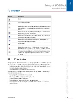
Page 120: ...lose current file Save project for saving the currently opened project Save project under for saving the project in another directory or under a different name Print Info about POSITool Establish connection to inverter MDS 5000 and FDS 5000 see section 7 1 Communication with MDS 5000 and FDS 5000 Establish direct connection SDS 5000 see section 7 2 6 Establishing a direct connection Establish Inte...

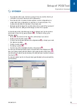
Page 121: ...ter screen or an assistant double click the applicable entry A configuration screen or a parameter screen is opened in the working area An assistant is not dependent on the working area and switches other processing areas to inactive The items Communication Diagnosis and Commissioning are described in the next few chapters Fig 5 2 Inverter entry The File menu has several items for management of an...

Page 122: ...ge inverters dialog screen are the inverters which exist in the currently opened project The buttons offer you the following options Move the inverters in the list of the current project up or down Delete inverter from the project Convert reverse documentations into configurations so that you can edit the data record offline Call the inverter settings Renaming inverter Insert a copy of the highlig...

Page 123: ... Right click the IGB entry and then select Properties in the context menu In the File menu select the Manage IGB entry Press the Properties button in the Manage IGB dialog You can also change the IGB designation and delete the IGB in the Manage IGB dialog Create an IGB entry 1 Open the menu File 2 Select the menu item New IGB A dialog screen for entering the IGB designation appears 3 Enter the des...

Page 124: ...arameter table is shown in the upper half of the screen A parameter with the following information is inserted in each line Coordinate Designation Current setting Default value Upper and lower limit value Unit Data type Read and write level Status PreRead or PostWrite function PDO mapping When a parameter is selected the parameter description appears in the lower half of the screen To change a par...

Page 125: ...on leads you to the parameters which can trigger actions please see the inverter operating manual for a description of the actions 1 2 Other manuals In addition to the buttons there is a selection list A certain parameter group can be selected with this function s Fig 5 4 Selection of the parameter groups When the parameter list is open in an axis area the parameters from the global area can also ...

Page 126: ...k can contain other blocks The block must be opened before the configuration structure within a block can be viewed The user clicks with the right mouse button on the block and select Open in the context menu which appears The next level in the configuration environment is then shown To reach a higher level the user clicks with the right mouse button on a free area in the configuration environment...

Page 127: ...ee chapter 6 5 7 2 Hierarchy view The hierarchy view shows a tree structure of the hierarchy of the current configuration see To indicate double click the applicable block in the configuration Fig 5 6 Hierarchy view 5 7 3 View menu In the View menu the user can adjust the indication of the status bar and the tool bar as well as the administrative area 5 7 4 Screen menu In the Screen menu the arran...

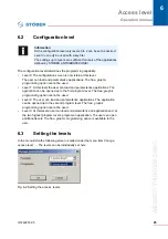
Page 128: ...ol offers an additional functionality which can hide parameters When the user clicks a line in the parameter list with the right mouse button the following context menu appears Fig 6 1 Fig 6 1 Changing parameter level In this menu the read or write level of a parameter can be changed separately Skillful setting of the parameter A10 0 can cause a lock at the same time When for example the value 1 i...

Page 129: ...s The application can be opened up to the second program level The free graphic programming option cannot be used Level 3 At this level a user can load and parameterize an application and at the two highest program levels program an application The user can open additional levels The free graphic programming option is available to the user 6 3 Setting the levels In the menu Extra the following scr...

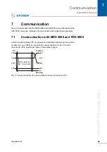
Page 130: ...ill be described separately 7 1 Communication with MDS 5000 and FDS 5000 Communication between PC and inverter is established with a serial connection A cable cat no 41488 is connected to a serial interface on the PC and to terminal X3 of the inverter as shown in the adjacent figure Fig 7 1 Serial connection to communication between inverter and PC 2 2 3 3 4 4 5 5 Housing Inverter PC FDS cable G3 ...

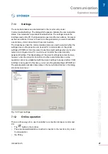
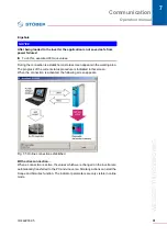
Page 131: ...ommunication or the global settings of POSITool It can be useful to use the project settings when an inverter network is configured on a PC on which each inverter has a permanently assigned interface The disadvantage of the project settings becomes obvious however when the project is transferred to other users Sometimes online operation cannot be established with the project settings because anoth...

Page 132: ...ool determines that inverter and PC have different configurations the dialog screen shown in appears You have the following choices Transfer the configuration in POSITool to the inverter or Load the configuration of the inverter to POSITool reverse documentation Fig 7 3 Establishing connection with different configurations If you want to check the differences between the applications press the Det...

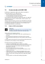
Page 133: ...ta record cannot be converted in a configuration or transferred again to the inverter Utilizing memory space When the configuration is loaded the memory requirements of the data record are compared with existing memory space on the inverter If it is certain that the data record can be stored POSITool does not give you a message If the expected memory utilization is 95 or more a message is indicate...

Page 134: ...e following choices Load the parameters from POSITool to the inverter or Load the parameters from the inverter to POSITool Fig 7 4 Establishing a connection for identical configurations If you want to check the differences between the parameters in POSITool and the inverter press the Details button POSITool then indicates the differences in a dialog screen in which the values of the parameters in ...

Page 135: ...ppears in the working area The progress of the current status procedure is indicated in this screen When the connection is activated the following screen appears Fig 7 5 Online connection established With active connection When a connection is active the values which were changed on the inverter are automatically transferred to the PC and vice versa Similarly actions can start the Scope and Simubo...

Page 136: ...and UDP IP protocol on port 37915 Remote maintenance without proxy server HTTP protocol on port 80 Remote maintenance with proxy server HTTP protocol on port of the proxy server You may be asked to share this port by the personal firewall Share these port for your firewall To do this contact your network administrator The IGB network must meet the following conditions A maximum of 32 SDS 5000s may...

Page 137: ...ns apply when integrating additional inverters into the network You have connected these inverters to the IGB network The inverters in the network must be receiving a 24 V power supply To start the integration the 24 V power supply of the inverter in the network must be turned on When the 24 V power supply is turned on the IGB network is restructured and up to 32 connected inverters will be integr...

Page 138: ...P address 128 206 17 177 with subnet mask 255 240 0 0 is entered for the network interface of the computer Subnet mask 1111 1111 1111 0000 0000 0000 0000 0000 The 12 numbers on the left of the IP address indicate the address of the subnet and must be identical in the IP address of the device The 20 number of the IP address on the right indicate the address of the computer in the subnet This sectio...

Page 139: ...ress and subnet mask of the PC network interface in the system control of the PC but POSITool offers an easier way of finding this information IP address 1000 0000 1100 1110 0001 0001 1011 0001 Network section must be identical in the device and PC Device section must be different in the device and PC Determining the IP address and subnet mask of the PC 1 In the Project view of POSITool open the N...

Page 140: ...pears 3 Click one of the two Determine settingsfrom network adapter buttons The following dialog screen appears 4 In the top part of the dialog screen select the network interface which is connected with the direct connection to the inverter The IP address and the subnet mask of the PC on this interface are indicated in the IP address field ...

Page 141: ...ter 1 Determine the IP address and the subnet mask of the PC network connection e g in the system control of your PC or in POSITool 2 Determine an IP address which is located in the same subnet as that of the PC 3 Using the operator panel of the gateway inverter enter this address in parameter A164 x Use A164 0 if the direct connection uses X3 A Use A164 1 if you connect the PC to X3 B 4 Check whe...

Page 142: ...ion 1 Click the button in the toolbar of POSITool The following dialog screen is displayed 2 Specify the IP address of the RJ45 connector that you have connected to the PC 3 Click the OK button You have established a direct connection and the IGB Display connected devices dialog screen is displayed The dialog screen shows all devices that are connected via the direct connection to the PC ...

Page 143: ...can select the inverters which are connected to the PC The possible targets in your project are shown in the second column 2 Highlight the line of the inverter entry in POSITool to which the data are to be written You can select an already existing inverter entry I1 Inverter1 or set up a new inverter entry new 3 In this line double click the first column Source IGB Please select A selection list a...

Page 144: ...ick the first column Source PC A selection list appears in which all inverter entries are listed which contain your project 4 Select the inverter entry which you want to write to the selected inverter 5 In this line double click the Action column A selection list appears in which you can set whether you want an automatic adjustment or whether the previously stored configuration and the parameters ...

Page 145: ...ress of parameters 8 1 Fault memory The last 10 events are recorded in the fault memory To obtain an exact overview of the fault situation the following values are read and stored at the time the fault occurred Fault Cause if it can be determined Operating time when the event occurred Active axis Device state Speed DC link voltage Current motor or device Temperature of the device Four freely selec...

Page 146: ... to be inserted the axis no must be stated e g 3 I09 Parameter I09 from axis 3 Parameter elements can also be entered e g A10 1 If the parameter is not entered correctly in the field it is not accepted When the free parameter list is open while a picture is being read with the Scope functionality the parameters entered in the list are included with the current values when the picture info is writt...

Page 147: ...mubox can be activated with the keyboard of the PC ESC button ESC key button Return Enter button Pfeiltaste nach links auf Ziffern oder Curserblock button Pfeiltaste nach rechts auf Ziffern oder Curserblock button Pfeiltaste nach oben auf Ziffern oder Curserblock button Pfeiltaste nach unten auf Ziffern oder Curserblock Hand button H key I O button I or 1 key 8 4 Scope The Scope function is used t...

Page 148: ...ked the picture is automatically read from the inverter when the status of the picture reaches Done Pictures are managed with Save Delete Info and Export A stored picture appears in the inverter entry under Commissioning It can be called again from there Names and remarks pertaining to a stored picture can be called under Info The dialog is automatically called during saving The measured values ar...

Page 149: ...th the pre trigger and the scanning time The scanning time determines the duration of picture It is indicated at the bottom left The trigger condition is used to define an event to which the picture time frame refers The pre trigger specifies which time period will be recorded before the event Example Total picture time 5 seconds Trigger Axis parameter E15 n motorencoder greater than 50 Rpm Pretri...

Page 150: ...isplayed 8 4 5 Channels When a picture is finished and read the channels can be selected via the buttons on the right hand side The recorded parameters are specified e g E91 with the occupied channels The display below the buttons contains the complete parameter designation of the selected channel The complete parameter designation is located under the buttons The second indication specifies the s...

Page 151: ...ft mouse button Enlarge reduce the scaling of the channel Ctrl key Auto scaling Indicate hide the channel Inverted indication of the channel Indicate the zero line of the channel Indication of a value in individual bits Can only be used for whole number parameters without positions after the decimal point and not with selection parameters Button Function ...

Page 152: ...is section and the function value at this time Changes can be made in the menu Extras POSITool options in the Scope dialog The horizontal value can be selected in 10 increments In addition to selecting the function value for the vertical value you can also set the scaling point to the vertical midpoint of the image or the zero line of the characteristic curve selection Picture midpoint and Zero li...

Page 153: ...ns are used for quick optimization The user can proceed as shown below 1 Set the reference value generator via the parameters D93 D94 and D95 and start the drive via the button 2 Make a picture of the movement with Scope 3 The parameters to be changed are entered in the Free parameter list and adjusted This procedure is repeated until the drive is optimally adjusted Button Function Switch on off t...

Page 154: ...ea showing the picture and an area showing additional information The print options offer a choice of black and white or color print dialog Options button Scope page The Scope commentary can also be printed as an option Fig 8 10 View of the print dialog Graphic area The graphic area includes the current display from Scope The curve number is specified via the curve on the zero point for a black an...

Page 155: ...ollowing information is indicated in this area Allocation of the eight channels with address designation scaling unit div and the identifier of an inverted presentation INV or a curve drawn to zero GND Scaling of the time axis time unit DIV Indication type Steps or Interpolated Trigger condition and scanning time pictures which were stored with an older version of POSITool are provided with a note...

Page 156: ...ocumentation Stored and current Scope pictures Scope pictures can also be printed directly from Scope The dialog offers several buttons This is where a preview of the printout can be indicated the printer and the page can be set up and the global settings can be switched to 9 2 Importing exporting of parameter values Parameter values can be imported and exported to a text file and archived These f...

Page 157: ...ch axis and global area Each area is identified with the following title U1 inverter1 Global Global The first sections indicate the resource identifier and the designation of the inverter from the configuration Assistant The resource identifier and designation of the axis or the global area from the configuration Assistant are indicated next Then the parameters are listed One parameter is indicate...

Page 158: ...arameters appears which exist in both the import file area and the target area The first section of the list shows the parameters which are identical in both areas Then the list appears with the parameters which are not set identically and the value in the target area which the import changed When the checkbox All parameter is activated in the dialog those parameters are also shown which exist exc...

Page 159: ...ctory on your PC 2 Copy the PDF documents to the directory which you want to call in POSITool You will find the documents on the product CD Electronics 5000 or at www stoeber de 3 Open POSITool 4 Open the Open the Options dialog screen of POSITool in the menu Extras POSITool options 5 Select the page Directories Fig 9 5 Integrating documentation 6 In the upper portion of the page set the directory...

Page 160: ...9 POSITool Options ID 442233 05 WE KEEP THINGS MOVING Operation manual 56 Fig 9 6 Listing of the PDF documents in the Project view ...

Page 161: ...tart screen is part of the start behavior of POSITool You can also choose between indication of the welcoming dialog standard a start screen with the last project or a blank POSITool screen 9 4 2 Memory options The memory options include the activation of Autosave and the setting up of a backup file A backup file is set up when an old status is overwritten during saving The backup file is given th...

Page 162: ...Notizen ID 442233 05 WE KEEP THINGS MOVING 58 ...

Page 163: ...10 65907393 eMail info stoeber cn www stoeber cn STOBER DRIVES INC 1781 Downing Drive Maysville KY 41056 Fon 1 606 7595090 Fax 1 606 7595045 eMail sales stober com www stober com STOBER DRIVES LTD Upper Keys Business Village Keys Park Road Hednesford Cannock WS12 2HA Fon 44 1543 458 858 Fax 44 1543 448 688 E Mail mail stober co uk www stober co uk STOBER Japan P O Box 113 002 6 chome 15 8 Hon koma...

Page 164: ...ronner Str 12 75177 PFORZHEIM GERMANY Tel 49 7231 582 0 Fax 49 7231 582 1000 E Mail mail stoeber de 24 h service hotline 49 180 5 786 323 Technische Änderungen vorbehalten Errors and changes excepted ID 442233 05 09 2013 442233 05 www stober com ...

Reviews: