JC-4s manual version 9.1 page 2
A: BEFORE YOUR START
First read this manual !
Some facts and hints for explanation.
1. Connect and use the provided control box before connecting it directly to your radio. By using this
control box you will understand very quickly how the tuner works.
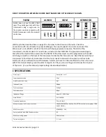
2. If you do not select an antenna output on the control box (switch in middle position) the coupler does
not accept a “tune start” commando and remains frozen.
3. If you do not connect an antenna to the selected output you will have a very low reception and IF the
coupler manages to tune, it may be damaged when raising power to transmit. (even with 100 Watt) So
always connect a wire or antenna during testing.
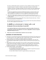
4. When the user is using only 1 antenna output (like A) he should NEVER connect it simultaneously to
both outputs. (So never connect A and B together)
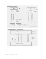
5. When a separate 12 volt power supply is used for the coupler, we must connect the “-“ terminal of
the separate power supply to the chassis of the transceiver. This is needed to return path of the power
supply is closed via the shield of the coaxial cable to the coupler. (see wiring diagrams in this manual)
6. When the 12 volt supply is not connected, both antennas outputs are disconnected and grounded! So
when the tuner is not in use the best possible protection of the coupler and transceiver is obtained.
7. During the operation of the tuner the coupler is still protected by a static discharge resistor and 2 x
600V ARC resistors in series.
B: TRANSCEIVER - COUPLER CONTROL CABLE:
4 x 0,50 mm or better if you use long lengths. (Brown, grey, yellow, black are the preferred colors but it
makes no difference). If you use a short control wire (< 25 meter) a normal UTP cable will do the job. But
it is common sense that UTP cable is not produced for 12 Volt DC voltage power feeding. UTP is used
only for low current data signals. For testing and short lengths you can use UTP but make use of all 8
wires. The control wire does not have to be shielded. But it is always better. As you can read that UTP is
doing the job almost
all cables can be used.
DISTANCE
2-20 m.
DIAMETER
0.50 mm
20-35 m.
0.75 mm
35-50 m.
1.00 mm
C: HOW IS THE CONTROL BOX WORKING AND CONNECTED?
This tuner JC-4 is controlled by 4 wires. These 4 wires you can easy find on the control box.
These 4 wires must be connected 1:1 from the control box to the tuner.
Function description of the 4 control wires:
Pin 1: (Brown) is + 12 volt DC power connection (NOT the connection to your power supply)


