background image

4. OPERATING AND ADJUSTING HOOK UNIT

After attached hook unit to mainframe, turn handle (No.6) backward, loosen nut M16 (No.11), Take allen

wrench,and insert the hole of the hexagon socket screw(No.12),then turn hexagon socket screw (No.12) , so that 
the distance between slide block(No.13) and hook frame can be adjusted , to fit with object’s thickness , to clamp 
the object ,then tighten nut M16. 

Turn handle (No.6) backward, Moving hook to appropriate position, Turn handle forward, the object can be 

clamped and can be moved. 

5. DRIVING SMART TOW TRACTOR

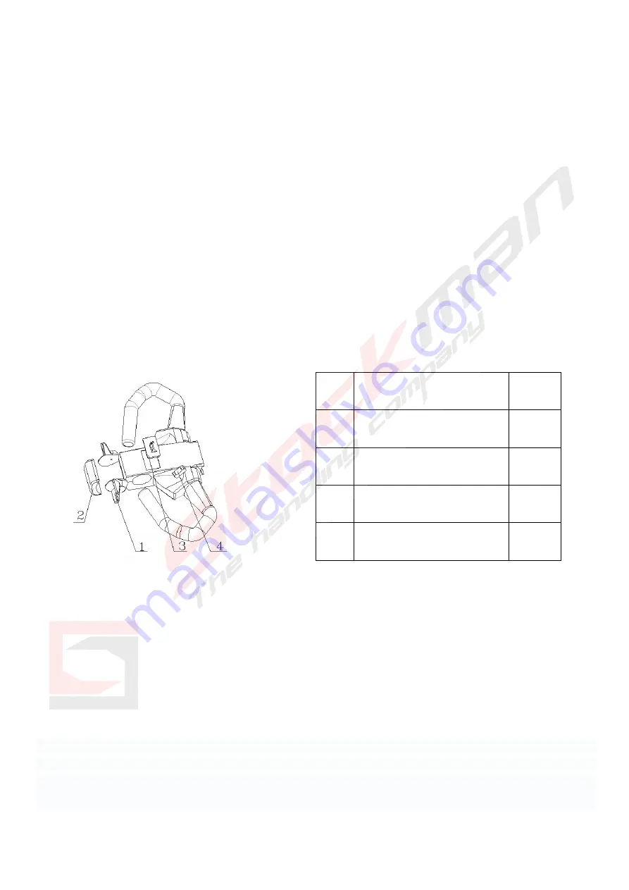
1) Speed knob.

Speed and acceleration are freely programmable. 

To operate the smart tow tractor moving forward or backward . turn the butterfly speed knob clockwise or counter 
clockwise gently and smoothly .   

 FIG 3 

2) Safety emergency switch (No.2 , fig 3)

The safety emergency switch prevents you from getting squeezed between the smart tow tractor and the obstacle . 
When you push it , the smart tow tractor will stop. 

3) Horn

4)High and slow speed switch .

This button allows you to freely switch fast and slow.

 Handle unit (No.1 and No.2,fig

5)Pull locating stud (No. 4) out locating plate (No. 2), and turn handle unit to appropriate position, then insert
locating stud into locating plate.

No. 

Description 

Quantity 

1. 

Speed knob 

2. 

Safety emergency switch 

3. 

Horn button 

4. 

High and slow speed switch 

Summary of Contents for SK N

Page 1: ...mation contained in this document is based on the data available at the time of printing The manufacturer reserves the right to modify its products at any time without notice obligation or constraint Please check our website for any updates 01 2021 ...

Page 2: ...tor Do not exceed the rated capacity Do not modify the smart tow tractor without the manufacturer s permission Do not add or remove weld or bend any parts Do not turn the smart tow tractor abruptly on a ramp Never use the smart tow tractor to transport people In case of a malfunction push the safety emergency switch No 2 fig 3 on the speed regulator 2 GERNERAL SPECIFICATION 3 ATTACH HOOK TO MAINFR...

Page 3: ...ook unit 1 No Description Quantity 1 Joint plate 1 2 Mainframe 1 3 Joint base 1 4 Screw M8X25 4 5 Spring washer 8 4 6 Restoration spring unit 1 7 Handle 1 8 Locking mechanism 1 9 Bushing 1 10 Shaft 1 11 Nut M16 1 12 Hexagon socket screw 1 13 Slide block 1 14 Hook frame 1 No Description Quantity ...

Page 4: ...d acceleration are freely programmable To operate the smart tow tractor moving forward or backward turn the butterfly speed knob clockwise or counter clockwise gently and smoothly FIG 3 2 Safety emergency switch No 2 fig 3 The safety emergency switch prevents you from getting squeezed between the smart tow tractor and the obstacle When you push it the smart tow tractor will stop 3 Horn 4 High and ...

Page 5: ...charged User takes out the charging cable 9 one end plugging in the charger plug 2 the other end plugging in the socket with 100 240VAC The charging indicator includes red and green LED Red LED shows that the power is charging Green LED shows that the power is full Charging full time is about 8 hours Fig 4 No Description Quantity No Description Quantity 1 Screw M4X15 2 6 Screw M5X20 4 2 Charger pl...

Page 6: ...NTENANCE It is recommended to sign a maintenance agreement with the smart tow tractor dealer who can also supply spare parts Contact our maintenance department or your smart tow tractor dealer for good and efficient maintenance service Safety instructions for maintenance Keep the working area clean without oil grease water etc Carry out the daily check maintenance before operating It is recommend ...

Reviews: