IMPORTANT
:
To avoid assembly problems follow these instructions exactly. Work Safely -
This assembly is
done with the Stockmaster standing upright.
Step 1
-
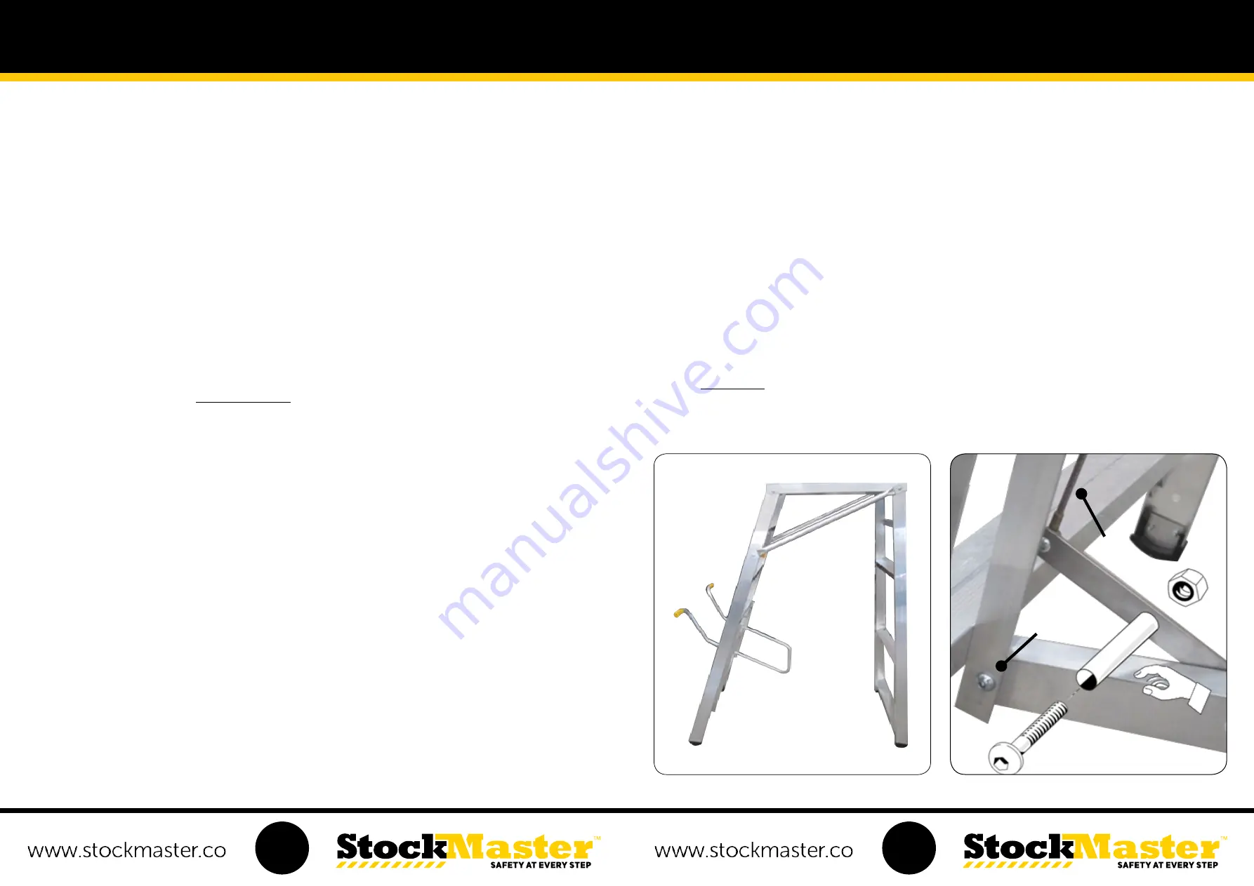
Fix the Mobilisation Rails (Rectangular Hollow Section - RHS) to the Frames at A & B (See illustration No. 1)
Step 2
-
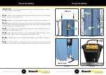
Using the M8 x 40 bolts, nuts and sleeves. Pass the bolt through the hole in the Frame Bracket at D, on the
Front Frame. Place a sleeve over the bolt and fit the Rectangular Hollow Section on the inside of the bracket. Secure
with a nut -
Finger tight only
. (See illustration No. 2)
Note:
The Mobilisation units are left & right with the
Link Cable C at end A
(See illustration No. 2)
. The bolt heads are
seen from the outer side of the ladder.
Step 3
-
Repeat Step 2 at position E on the Rear Frames -
Finger tight only.
(See illustration No. 3)
Step 4
-
One at a time, fix the
3 x No Lock Castors
and Castor Mounting Angles to the Mobilisation Channels -
One
Directional Lock castor is supplied. Use this Castor at Frame end A
. Pass an M12 x 40 hex head bolt through the
Mobilisation Channel and locate the Castor Mounting Angle over the bolt. Fit the Castor and then a Washer placed inside
the castor body. Secure the Castor with the nut. Tighten the nut with the Spanner provided. The head of the bolt will
refrain from turning as its held in a fixed position between the channel flanges.
(See illustration No. 4)
Note:
Castor Mounting Angles have two sets of mounting holes. For sizes 4 and 5 use the inside holes. For sizes 6
and larger, use the outside holes.
Step 5
-
Press down on the Black Locking Tab On the Directional Lock Castor. Fix the castor as per step 4 with the
Tab positioned in the direction of the arrow. Hold the Castor in the position illustrated as you tighten. (See illustration
No. 5)
Step 6
-
Attach the Mobilisation Link Cable to the Control Handle. Fit a Clevis Pin through the lower hole in the
Control Handle. Lift up the Link Cable C. Fit it over the Clevis Pin and secure with an “E” Clip on the inside ring of the
Clevis Pin. (See illustration No. 6)
Mobilisation Assembly
Step 7
-
Assemble the 5th wheel assembly (See illustration No. 7)
A). Feed the 62mm long flanged bush from the underside of the yellow buffer and through the top of the tube
B). Fit the 12mm Washer to the M12 x 150 hex bolt and feed it down through the bush
C). Place spring over the bolt
D). Screw the smaller threaded bush (flanged sidedown) all the way up the bolt thread.
(Hand tighten to firm only)
E). Fit the Castor to the bolt and then place a washer inside the castor body. Secure the Castor with the nut. Place the
Spanner over the nut, hold the nut in a fixed position and tighten the bolt with the Hex Key untill firm.
Step 8
-
Slide the Buffer Tube into position and ensure that it is square to the Mobilisation. Align the holes in the
Buffer Tube and Mobilisation RHS at E and F. (Use a screwdriver blade to line up the holes) Using the Nylon Anchors at
E and F. Hammer in the steel pins to fix the Buffer Tube to the Mobilisation Rails
Step 9
-
Ensure the Ladder is standing on a level surface. Stand on the first step taking hold of ladder frame and
flexing it so all four feet sit firmly on the floor. When there is no evidence of rocking, tighten the four Mobilisation to
Frame fixings using the Hex Key and Spanner provided. Now tighten the remaining 10mm bolts in the Ladder Frames
using the
Hex Key only.
(Hold the nut in a fixed position with the spanner. Do not rotate the nut.)
Illustration 1
Illustration 2
A
B
A
D
C
M8 x 40
19
20


