13
13 Installation guide
(Page 2 of 2)
Spreader Plates
The machines
have 8 or 10 outlet tubes, feed hoses can be split with the black “ Y” connectors provided, to
give 16 or 20 spreader plates
. Depending on the implement width and if you require a broadcast or band
sown effect, use as many outlets as required, with or without the spreaders.
Plan the positioning of the pipes/spreader plates to be equal distant across the width of your implement. If
using the black plastic “Y” connectors ensure they are fitted above the spreader plate using as short a run of
flexible hose to the plates a possible, whilst still providing a smooth flow and of being equal length. It is
recommended that a straight 30cm section of pipe is utilised prior to the “Y” connector to ensure an even
split of product.
Flexible hose from these connectors then runs to the outlet pipes on the Turbo Jet. Aim to route all these
hoses smoothly and generally downhill from the hopper to the spreader plate, avoiding severe bends and
uphill runs.
C Section Rail
The spreader plates themselves are mounted to the “C” section rails, 4 x 2m lengths per machine are
supplied. These can be cut down to suit the implement width. The “C” section rails can be attached to the
implement using the supplied straight brackets, two per rail, which can be welded or bolted into position.
The spreader plates slide along the rails to give the planned spacing, and lock into position using the integral
bolts. It is generally better to position the spreader plates facing to the rear of the implement as this can
prevent wet mud or tilth being thrown up into the mouth of the spreader causing blockages, especially if
positioned close behind the tractor wheels, roller, or discs.
Feed Hose
A 30m coil of flexible feed hose is supplied with each Turbo Jet (with extra hose available if required)
This requires cutting into lengths according to the positioning of the hopper and spreader. Ensure all hose
runs are as short as possible whilst giving a smooth downhill route to the spreader plates. Avoid kinks,
severe bends or uphill runs. Plan and measure the individual tube runs before cutting, fit the hose clips to
the Y connector tails.
Summary of Contents for Turbo Jet 10 i-CON
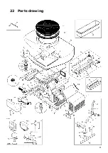
Page 22: ...22 22 Parts drawing 5 ...
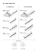
Page 26: ...26 26 Feed roller kits ...
Page 29: ...29 29 Notes page ...
Page 30: ...30 ...


