20
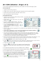
20 i-CON Calibration (Page 1 of 2)
You will need the supplied plastic calibration tray, and an accurate set of scales which weighs in grams
At the Junction Box
1. Switch the fan OFF at the junction box
2. Release the two over-centre catches and drop the hinged panel under the cassette manifold
3. Position the collection tray directly underneath to catch the seed
4. Place a few kilograms of seed in the hopper
At the ICON Cab Console
1. Switch the head unit ON via the left hand side push button – wait until the start-up routine has finished and
displays the main “home screen”
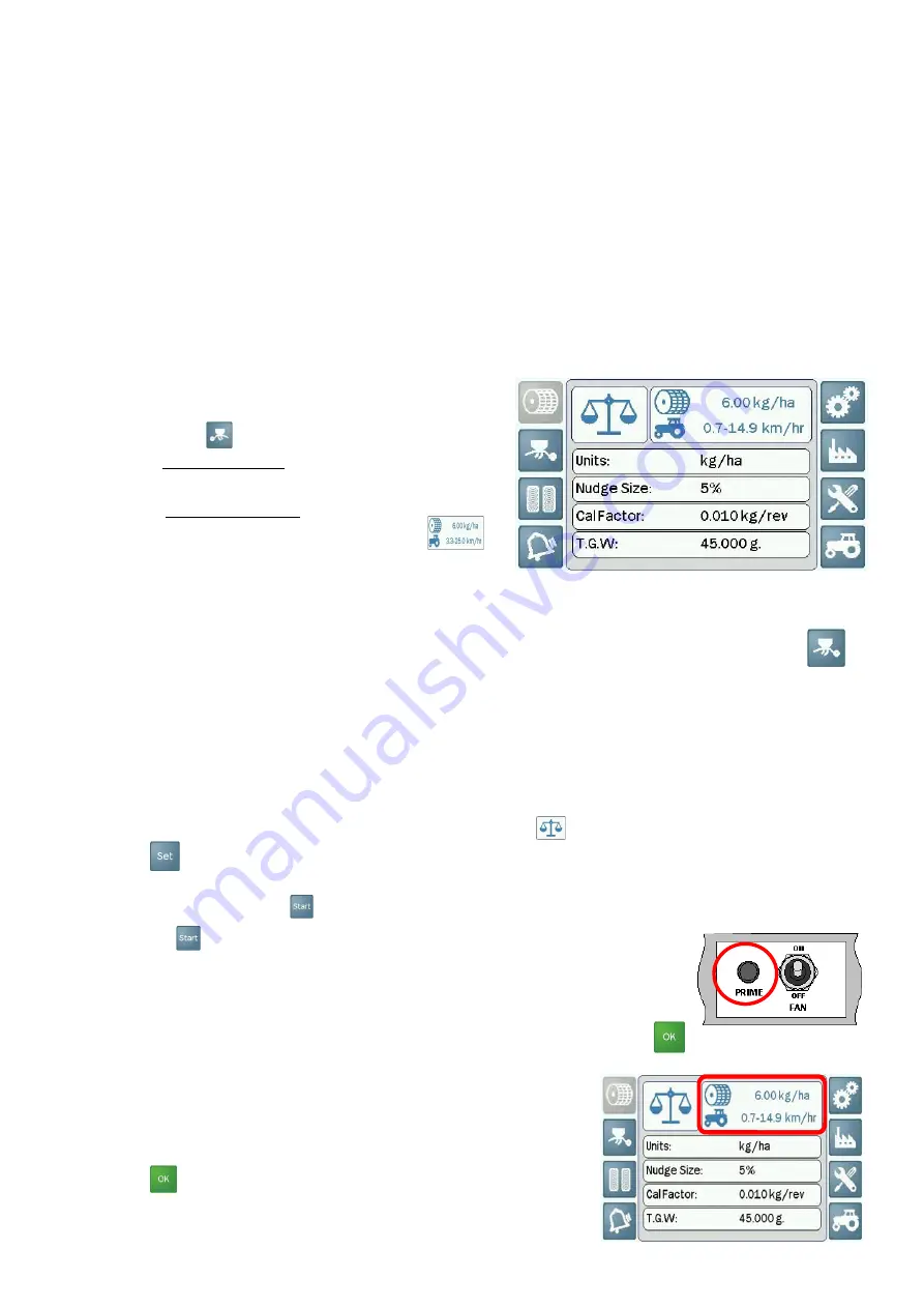
2. Scroll through to the Setup Menu and select the
Applicator Icon
3. Adjust the implement width accordingly - refer to the
RDS manual, page 25, section 3.3, Set Implement Width
4. Ensure the correct application rate is entered
– select and adjust accordingly, refer to the
RDS manual, page 21, section 3.1, Setting the
Application Rate
5. Ensure the feed roll setup is appropriate for the intended seed type, application rate and forward speed
range for application
6.
Ensure that if sowing grass or cover crop mixes the agitator motor function is enabled
via
refer to the RDS manual, page 25, section 3.3, Applicator Setup
7. The instrument calculates the calibration factor from the working width, target application rate, and the
metered weight delivered whilst calibrating. If however as a result of the calibration routine, you find that
you cannot achieve your desired field speed, displayed in the top right corner of the screen, then
re-configure the feed roll assembly and repeat the calibration procedure
8. Prime the feed rolls with product by pressing and holding briefly the prime button on the junction box - this
will ensure a higher initial calibration accuracy, empty the contents of the tray back into the hopper
9. For an
Auto Calibration
from the Product Setup page, touch
10. Touch
and enter the quantity that you wish to dispense for calibration purposes. You can enter the
quantity in grams if preferred. The CAL factor will however, still be calculated in kg/rev
11. Touch on the screen page
12. After the
key the motor runs at the calibration speed (calculated from
the Simulated Forward Speed, Width, Application Rate and current calibration
factor)
13. The dispensed weight (based on the current calibration factor) is displayed
14. Weigh the product dispensed and then enter the measured weight, and press
15. A new calibration factor is then re-calculated and displayed
16. Your in field min and max speeds will be displayed as per the image
to the right hand side. If you find that you cannot achieve your
desired field speed, then re-configure the feed roll assembly and
repeat the calibration procedure (see page 18 for more details)
17. Touch to save the new factor, it is advised to repeat the
calibration 2 more times to ensure accuracy
Summary of Contents for Turbo Jet 10 i-CON
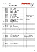
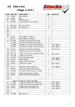
Page 22: ...22 22 Parts drawing 5 ...
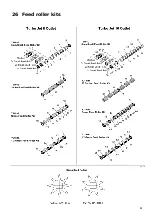
Page 26: ...26 26 Feed roller kits ...
Page 29: ...29 29 Notes page ...
Page 30: ...30 ...


