background image

Safety Alert Symbol:

This symbol 

Indicates danger, warning or caution. 

Attention is required in order to avoid serious per-
sonal injury. The message that follows the symbol 
contains important information about safety.

Signal Word:

Signal words are

 distinctive words used throughout 

this manual that alert the reader to the existence and 
relative degree of a hazard.


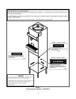
CAUTION

The signal word “CAUTION” 

indicates a potentially 

hazardous situation, which, if not avoided, may result 
in minor or moderate injury and equipment/property 
damage.

A Few Words About Safety

Safety Information

 Read and understand the entire manual before 
operating or maintaining Stoelting equipment.

This manual provides the operator with information 
for the safe operation and maintenance of Stoelting 
equipment. As with any machine, there are hazards 
associated with their operation. For this reason safety 
is emphasized throughout the manual. To highlight 
specifi c safety information, the following safety defi ni-
tions are provided to assist the reader.

The purpose of safety symbols is to attract your at-
tention to possible dangers. The safety symbols, and 
their explanations, deserve your careful attention 
and understanding. The safety warnings do not by 
themselves eliminate any danger. The instructions 
or warnings they give are not substitutes for proper 
accident prevention measures.

If you need to replace a part, use genuine Stoelting 
parts with the correct part number or an equivalent 
part. We strongly recommend that you do not use 
replacement parts of inferior quality.


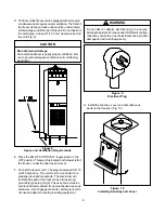
WARNING

The signal word “WARNING” indicates a potentially 
hazardous situation, which, if not avoided, may result 
in death or serious injury and equipment/property 
damage.

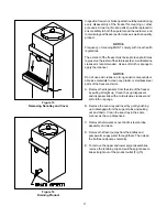
CAUTION

The signal word “CAUTION” not preceded by the 
safety alert symbol indicates a potentially hazardous 
situation, which, if not avoided, may result in equip-
ment/property damage.

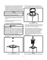
NOTE (or NOTICE)

The signal word “NOTICE” indicates information or 
procedures that relate directly or indirectly to the 
safety of personnel or equipment/property.

Summary of Contents for 100CA

Page 1: ...Model 100FA 100CA 2217GA OPERATORS MANUAL Manual No 513653 Mar 2010...

Page 2: ......

Page 3: ...built prior to date of change DO NOT ATTEMPT to operate the machine until instructions and safety precautions in this manual are read completely and are thoroughly understood If problems develop or q...

Page 4: ...ecific safety information the following safety defini tions are provided to assist the reader The purpose of safety symbols is to attract your at tention to possible dangers The safety symbols and the...

Page 5: ...ON 9 3 1 Operator sSafetyPrecautions 9 3 2 OperatingControlsandIndicators 9 3 3 Draining the Freezer For Disassembling and Cleaning 10 3 4 Disassembly and Cleaning of Freezer Parts 10 3 5 Sanitizing T...

Page 6: ...14 DrainingProduct 11 15 RemovingSpigotAssembly 12 16 RemovingSpigotO RIngfromSpigotBody 12 17 Cut away View of Spigot Assembly 12 18 RemovingDriveCapandO Ring 13 19 RemovingSealerRing 13 20 Removing...

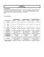
Page 7: ...7 6 cm 58 147 3 cm 66 167 6 cm depth 29 1 2 74 9 cm 35 1 2 90 2 cm 15 38 1 cm 21 53 3 cm 15 38 1 cm 21 53 3 cm Weight 142 lbs 64 4 kg 200 lbs 90 7 kg 140 lbs 63 5 kg 165 lbs 74 8 kg 160 lbs 72 5 kg 18...

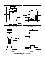
Page 8: ...2 Figure 1 Model 100CA Front Figure 3 Model 100FA 2217GA Front Figure 2 Model 100CA Side Figure 4 Model 100FA 2217GA Side NOTE Figures in parenthesis are in centimeters AIR OUT...

Page 9: ...later advise the carrier within 10 days and request inspection The customer must place claim fordamagesand orshortagesinshipmentwiththecarrier 2 3FREEZERINSTALLATION Installationofthefreezerinvolvesmo...

Page 10: ...S SOTHEYUNDERSTANDHOWTOSAFELY OPERATETHISEQUIPMENT DO NOT REMOVE DEFACE OR PAINT OVER ANY DECALS THEY ARE THERE FOR YOUR SAFETY CAUTION Behind Sani tray Behind Sani tray THIS DEVICE MUST BE PLUGGED IN...

Page 11: ...UNDERSTANDHOWTOSAFELY OPERATETHISEQUIPMENT DO NOT REMOVE DEFACE OR PAINT OVER ANY DECALS THEY ARE THERE FOR YOUR SAFETY CAUTION Affixed to condenser shroud Affixed to condenser shroud THIS DEVICE MUST...

Page 12: ...nnect the power cord The plug is designed for 115 volt 15 amp duty The unit must be connected to a properly grounded receptacle The electrical cord furnished as part of the freezer has a three prong g...

Page 13: ...ENSERS To adjust the cup dispensers install the size cup desired into the dispenser and turn the wing nut on the dispenser mounting bracket until enough tension is applied to the rim of the cup to kee...

Page 14: ...8...

Page 15: ...cted G Do not operate under unsafe operating conditions Never operate the freezer if unusual or excessive noise or vibration occurs 3 2OPERATINGCONTROLSANDINDICATORS Beforeoperatingthefreezer itisrequ...

Page 16: ...pressor from damageduetoexcessiveheadpressure Whentripped the lever will be out push to reset E SPIGOT ASSEMBLY Dispensing of frozen mix is done by the SPIGOT ASSEMBLY By pulling the spigot plunger ou...

Page 17: ...clean any plastic or stainless steel parts of the freezer exterior A Remove the dispensers from the side of the freezer by pulling straight up Clean the cup dispensers and dispenser lids with a mild a...

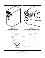
Page 18: ...15 RemovingSpigotAssembly Figure 16 Removing Spigot O Ring from Spigot body Figure 17 Cut away View of Spigot Assembly KNOB O RING SPRING RETAINERCAP SHAFT PLUG ASSEMBLY SPLASHDEFLECTOR FORSPIGOT SHA...

Page 19: ...freezermustbedisconnected from electrical supply before removing any access pan els Only a qualified service technician may remove accesspanels Failuretodisconnectpowerbeforeservic ing could result in...

Page 20: ...divider plate from the agitator fingers andremove Fig 21 7 Place all loose parts in a pan or container and take them to the wash sink filled with warm soapy water forcleaning CAUTION Do not damage pa...

Page 21: ...after the freezer is clean and just before the product cylinder is filled with mixed neutral base Sanitizingthenightbeforeisnoteffective However you should always clean the freezer and parts after use...

Page 22: ...de the assembly down the vertical center post and lock Fig 25 Figure 25 Installing Divider Plate and Agitator Assembly 8 Install the sealer ring by squeezing the looped section and sliding down into t...

Page 23: ...ubbles will rise to the top of the liquid in the product cylinder When no morebubbles rise to the top the air trapped under the dividerplatehasbeenremoved Pourthecontentsofthe container back into the...

Page 24: ...freezer damage and could void the warranty CONDENSERCLEANING 1 For the floor models remove the sani tray and insert Remove the two phillips head screws from the lower front panel and pull panel down a...

Page 25: ...19 Figure 28 External Parts To Be Cleaned CUP DISPENSERS AND LIDS LIQUIDLEVELINDICATOR SANI TRAYANDINSERT ALL PANELS COVERS FLAVORBOTTLES...

Page 26: ...20...

Page 27: ...C E L E N O I T U A C L A C E D 7 0 1 4 2 3 S T R A P G N I V O M N O I T U A C L A C E D 3 1 1 4 2 3 G U L P D E D N U O R G N O I T U A C L A C E D 5 3 1 4 2 3 H C T I W S Y T E F A S E L G G O T L...

Page 28: ...22...
Page 29: ...notice of any claimed breach of warranty within the applicable warranty period and c delivers the affected equipment to Stoelting or its designated service location in its original packaging crating...

Reviews: