5
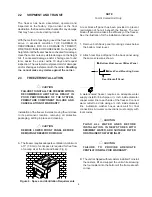
C. Accurate leveling is necessary for correct drainage
of freezer barrel to insure correct over-run and flow.
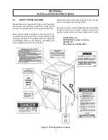
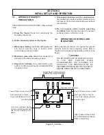
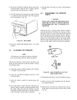
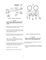
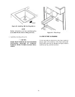
Place a spirit level on top of the freezer at each
corner to check for level condition (Fig. 5). If
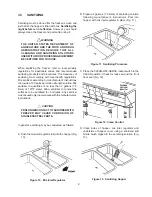
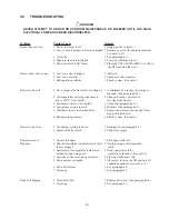
adjustment is necessary, level the freezer by turning
the casters in or out (Fig. 6).
Figure 6. Caster Adjustment
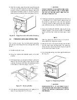
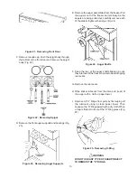
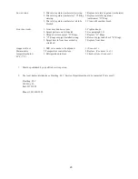
Figure 7. Connecting Permanent Wiring
C. For location of proper electrical connections, refer
to Figure 7.
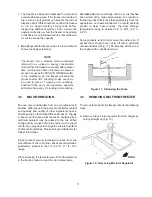
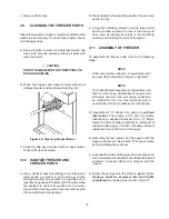
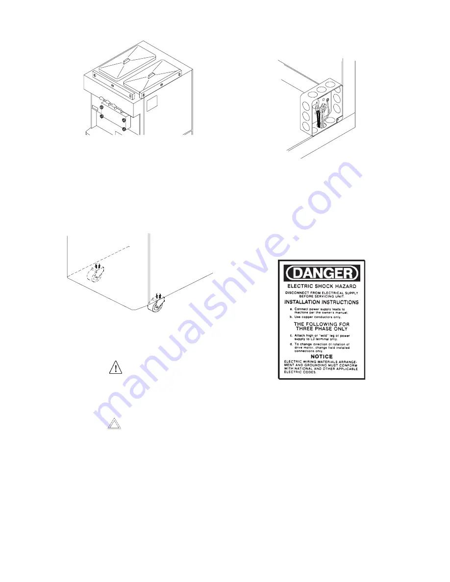
Figure 8. Danger Decal
Figure 5. Leveling Freezer
2.4
ELECTRICAL CONNECTIONS
WARNING
BEFORE INSTALLATION OF ANY CABLE IN
THE FREEZER, DISCONNECT THE FREEZER
FROM ITS ELECTRICAL SUPPLY SOURCE.
CAUTION
ROUTE ELECTRICAL CABLE SO THAT IT
CANNOT BE ACCIDENTALLY DAMAGED BY
PINCHING, CRUSHING, ETC.
A. Connect freezer to a properly grounded 208/230 volt
(AC), source of electricity.
B. To access the electrical boxes, remove the two
Phillips head screws on the left and right side panels.
Then pull the panel down and out.
NOTE
When supply voltage is less than 218V, reconnect
transformer. Switch orange and red wires from
transformer at the terminal strip and cap blue wire.
D. Please read decal located on lower electrical box
cover (Fig. 8)
The model 4231 freezer is two individual freezers in a
common enclosure.
EACH SIDE MUST BE
CONNECTED INDIVIDUALLY. EACH SIDE MUST
HAVE ITS OWN ELECTRICAL SUPPLY.
When making
the electrical supply connections,
YOU MUST
MAINTAIN STRAIGHT POLARITY FROM SIDE TO
SIDE.
E. Check the auger shaft rotation by placing the MAIN
DRIVE switch in the CLEAN position. Auger shaft
rotation is clockwise as viewed through the clear
plastic front door. If the rotation is not clockwise, turn
the main electrical power OFF. Then reverse L1 and
L3 electrical power lines to the junction box (three
phase only). Re-check auger shaft rotation.


