21
3. Recover the refrigerant charge, and then leave a port
open to prevent pressure buildup when applying heat.
WARNING
BOTH SUCTION SIDE SOLENOIDS MUST BE
ACTIVATED FOR PROPER PURGING OF
SYSTEM. USE POWER CORD PART NO.
430119
OR EQUIVALENT FOR DIRECT
CONNECTION.
4. Remove any insulation from the T.X.V. and immediate
surrounding lines.
5. Remove or push back any foam insulation from
surrounding lines.
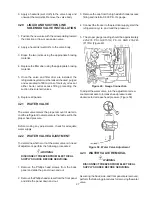
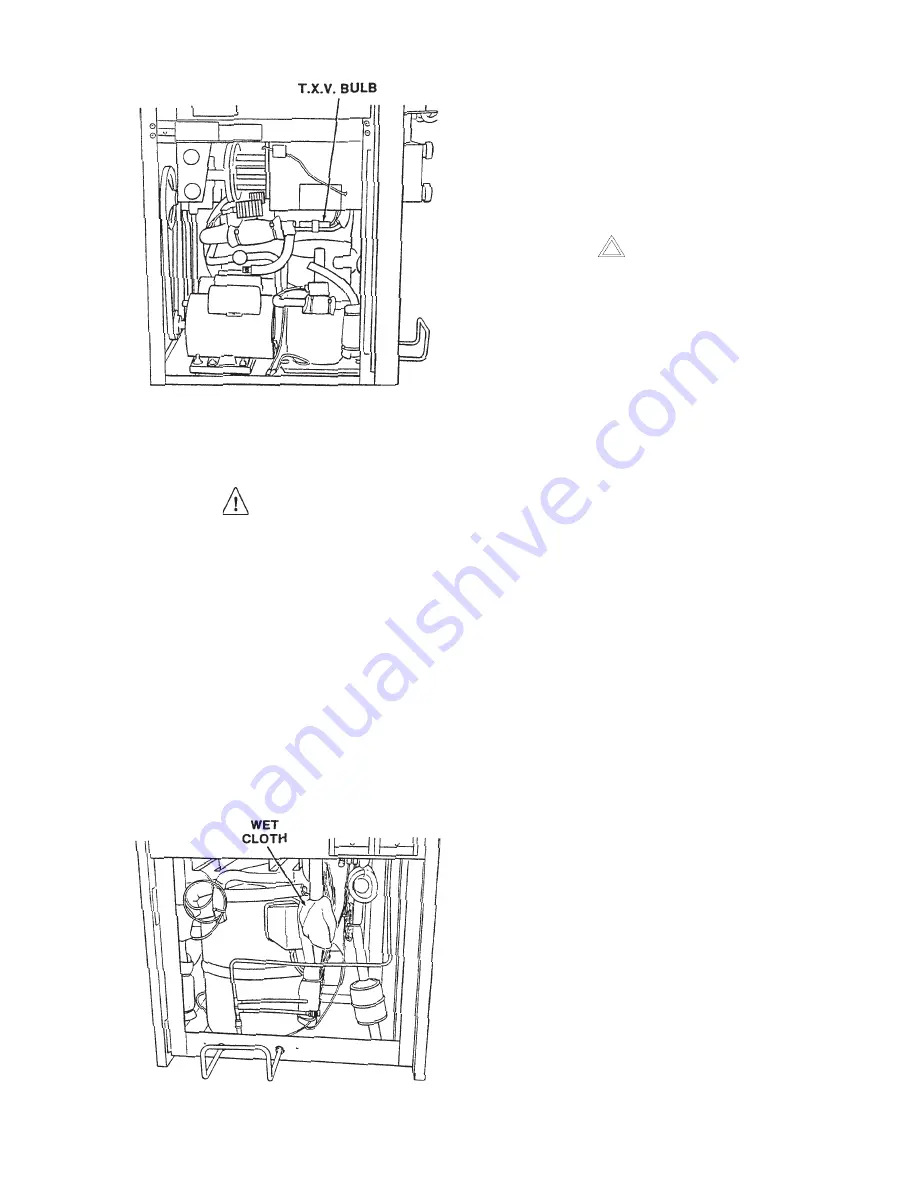
6. Apply a heatsink (wet cloth) to the valve dome (Figure
36).
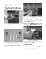
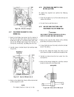
Figure 35. Bulb Removal
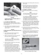
Figure 36. T.X.V. Removal
7. Unsweat the suction line and liquid line from the T.X.V.
and remove.
4.8
T.X.V. INSTALLATION
To replace the T.X.V., perform the following proce-
dures:
CAUTION
WHEN PLACING THE T.X.V., A HEATSINK (WET
CLOTH) MUST BE USED TO PREVENT
DAMAGE TO THE VALVE.
1. Position the T.X.V. with heatsink so the liquid line and
suction line correspond with the proper valve ports.
2. Braze the liquid line and suction line to the T.X.V. by
using the appropriate brazing material.
3. Remove the heatsink from the T.X.V.
4. Replace any foam insulation to the surrounding lines.
5. Replace any insulation to the T.X.V. and surrounding
areas.
NOTE
The liquid line from the condenser is bonded to
the suction line to provide a heat exchange to help
protect the compressor from liquid slugging. This
also assures that sub-cooled liquid is being
supplied to the expansion devices.
Summary of Contents for E131G
Page 1: ...Model E131G F131G SERVICE MANUAL Manual No 513537 3 Mar 2004...
Page 2: ......
Page 14: ...6...
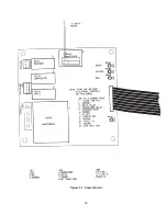
Page 38: ...30 Figure 51 Power Board...
Page 39: ...31 Figure 52 Program Module...
Page 54: ...46...
Page 66: ...58...
Page 68: ...60...
Page 69: ...61 666786...
Page 70: ...62...
Page 71: ...63...
Page 72: ...64...
Page 73: ...65...
Page 74: ...66...
Page 75: ...67...
Page 76: ...68...
Page 77: ...69...
Page 78: ...70...
Page 80: ......


