23
NOTE
The ideal E.P.R. valve setting (69-71 P.S.I.G.) will
not allow mix to freeze to the walls of the hopper.
5. If the pressure gauge reading does not fall between
the 69-71 P.S.I.G. parameters, proceed with the
following steps.
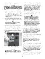
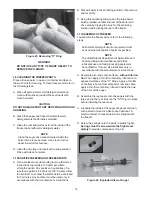
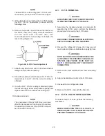
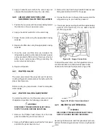
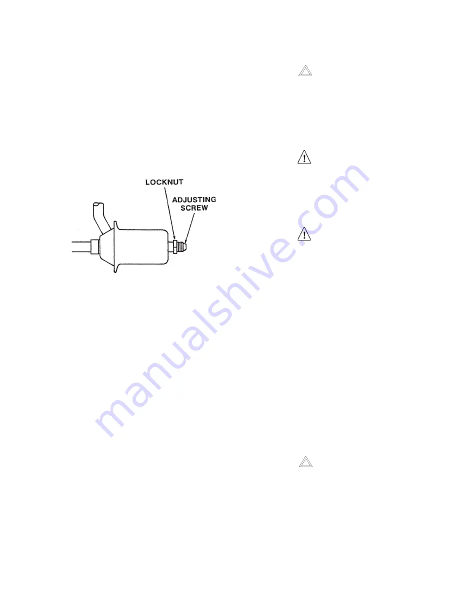
6. Remove the plastic cap and loosen the locknut on
the E.P.R. valve. Then, using a small screwdriver,
turn the valve stem one-forth (90°) turn
counterclockwise for more cooling or clockwise for
less cooling (Figure 40).
7. Allow the system to level out for 3-5 minutes before
taking another pressure reading.
8. Should the readings not fall between 69-71 P.S.I.G.,
repeat steps 6 and 7 until the correct reading is
obtained.
9. Once the 69-71 P.S.I.G. reading is obtained, tighten
the locknut snugly, remove the pressure gauge, and
replace the E.P.R. Schrader access fitting cap.
10.Replace all panels.
NOTE
The compressor ON and OFF times can also
affect the temperature of the hopper. Procedures
for adjusting compressor ON and OFF times will
be discussed in Section 5.
Figure 40. E.P.R. Valve Adjustment
4.11
E.P.R. REMOVAL
CAUTION
A HEATSINK (WET CLOTH) MUST BE USED
TO PREVENT DAMAGE TO THE VALVE.
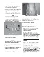
1. Assuming the necessary panels are removed for
adjusting the E.P.R. valve, perform the following
procedures for removing the E.P.R. valve.
WARNING
DISCONNECT FREEZER FROM ELECTRICAL
SUPPLY SOURCE BEFORE SERVICING.
2. Recover the refrigerant charge, then leave a port
open to prevent pressure buildup when applying heat.
WARNING
BOTH SUCTION SIDE SOLENOIDS MUST BE
ACTIVATED FOR PROPER PURGING OF
SYSTEM. USE POWER CORD PART NO.
430119
OR EQUIVALENT FOR DIRECT
CONNECTION.
3. Remove the foam insulation from the surrounding
lines.
4. Apply a heatsink (wet cloth) to the E.P.R. valve.
5. Unsweat the two refrigeration lines.
6. Remove the E.P.R. valve with the heatsink.
4.12
E.P.R. VALVE INSTALLATION
To replace the E.P.R. valve, perform the following
procedures:
CAUTION
WHEN REPLACING THE E.P.R. VALVE, A
HEATSINK (WET CLOTH) MUST BE USED TO
PREVENT DAMAGE TO THE VALVE.
Summary of Contents for E131G
Page 1: ...Model E131G F131G SERVICE MANUAL Manual No 513537 3 Mar 2004...
Page 2: ......
Page 14: ...6...
Page 38: ...30 Figure 51 Power Board...
Page 39: ...31 Figure 52 Program Module...
Page 54: ...46...
Page 66: ...58...
Page 68: ...60...
Page 69: ...61 666786...
Page 70: ...62...
Page 71: ...63...
Page 72: ...64...
Page 73: ...65...
Page 74: ...66...
Page 75: ...67...
Page 76: ...68...
Page 77: ...69...
Page 78: ...70...
Page 80: ......

