25
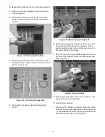
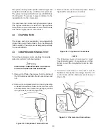
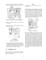
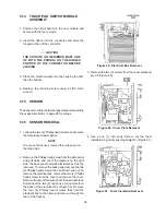
2. Position the capillary tube and braze the tube to the
hopper using the appropriate material. (Figure 43)
3. Replace the foam insulation to the hopper inlet
connections.
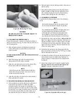
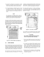
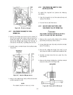
4. Replace filter drier using the appropriate brazing
material (Figure 44).
NOTE
Freezer barrels must not contain frozen product
for this test.
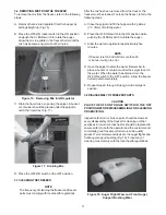
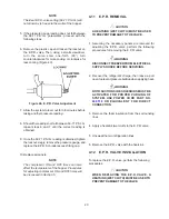
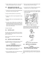
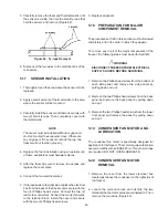
1. To check the suction line solenoid valve seats, we
must keep the liquid line solenoid open. Use power
cord, Part No.
430119,
or equivalent, for direct
connection (Figure 45). Then attach a low side
pressure gauge to the access fitting after the
expansion valve. Force the opposite side to run. If
the pressure drops more than 3 PSI in 30 seconds
on the side not calling for refrigeration, the suction
line solenoid valve seat leaks and should be replaced.
Repeat the procedure for the other side.
Figure 45. Power Cord
Figure 43. Capillary Tube and Drier Assembly
Figure 44. Filter Drier
5. Once the capillary tube drier assembly and filter drier
are installed, the refrigeration system must be leaked
checked, purged and evacuated to 500 microns of
mercury or less at either barrel outlet access fitting
preceding the suction line solenoid valves.
4.16
SOLENOID VALVE
Some models have suction line and liquid line solenoid
valves. To check for leaking valve seats, follow the
procedure outlined below.
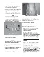
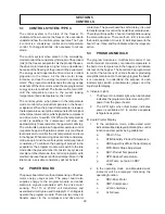
2. To check the liquid line solenoid valve seats, we must
disconnect one of the electrical lines from each of
the liquid line solenoids. Protect the terminal end of
the disconnected electrical line with a piece of
electrical tape. Then, connect the low side pressure
gauges to the access fittings after the expansion
valves. Force the left and right sides to run by turning
the OFF/ON switch to the ON position and opening
the spigots. The gauges should show approximately
9” of vacuum after 1 minute. If the gauge does not
reach 1” of vacuum in 1 minute and hold, you may
have a leaking solenoid valve seat or leaking valves
in the compressor. You can determine which solenoid
valve is leaking by watching the pressure rise in each
of the barrels. The barrel with the greatest pressure
rise should have the leaking solenoid valve seat
(Figure 46).
Summary of Contents for E131G
Page 1: ...Model E131G F131G SERVICE MANUAL Manual No 513537 3 Mar 2004...
Page 2: ......
Page 14: ...6...
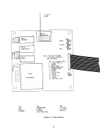
Page 38: ...30 Figure 51 Power Board...
Page 39: ...31 Figure 52 Program Module...
Page 54: ...46...
Page 66: ...58...
Page 68: ...60...
Page 69: ...61 666786...
Page 70: ...62...
Page 71: ...63...
Page 72: ...64...
Page 73: ...65...
Page 74: ...66...
Page 75: ...67...
Page 76: ...68...
Page 77: ...69...
Page 78: ...70...
Page 80: ......

