27
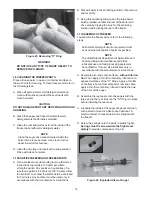
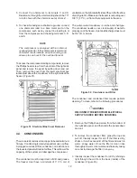
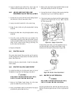
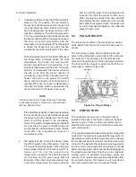
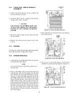
Figure 50. Water Valve Adjustment
6. Apply a heatsink (wet cloth) to the valve body and
unsweat the two joints. Remove the valve body.
4.20
LIQUID AND SUCTION LINE
SOLENOID VALVE INSTALLATION
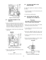
1. Position the new valve with the arrow pointing toward
the direction or flow or expansion valve.
2. Apply a heatsink (wet cloth) to the valve body.
3. Braze the two joints using the appropriate brazing
material.
4. Replace the filter drier using the appropriate brazing
material.
5. Once the valve and filter drier are installed, the
refrigeration system must be leaked checked, purged
and evacuated to 500 microns of mercury or less at
either barrel outlet access fitting preceding the
suction line solenoid valves.
6. Replace all panels.
4.21
WATER VALVE
The water valve meters the proper amount of water to
cool the refrigerant to a temperature that will result in the
proper head pressure.
Before making any adjustments, check for adequate
water supply.
4.22
WATER VALVE ADJUSTMENT
To determine whether or not the water valve is in need
of adjustment, perform the following procedures:
WARNING
DISCONNECT FREEZER FROM ELECTRICAL
SUPPLY SOURCE BEFORE SERVICING.
1. Remove the Phillips head screws from the back
panel and slide the panel down and out.
2. Remove the Phillips head screws from the front panel
and slide the panel down and out.
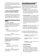
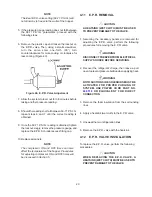
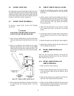
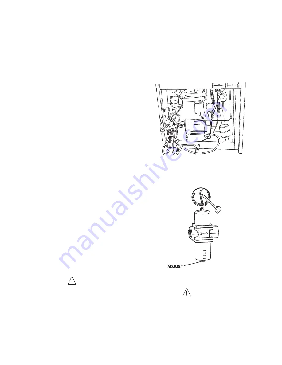
Figure 49. Gauge Connection
3. Remove the cap from the high side Schrader access
fitting and install a 0-500 P.S.I.G. gauge.
4. Connect the freezer to the electrical supply, start the
refrigeration cycle, and read the pressure.
5. The proper gauge reading should be approximately
225-235 P.S.I.G.(E131G) P.S.I.G. AND 235-245
(F131G) (Figure 49).
To adjust the water valve, turn the adjustment screw
counterclockwise to increase head pressure and
clockwise to decrease head pressure (Figure 50).
4.23
WATER VALVE REMOVAL
WARNING
DISCONNECT FREEZER FROM ELECTRICAL
SUPPLY SOURCE BEFORE SERVICING.
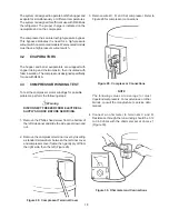
Assuming the back, side, and front panels are removed,
perform the following procedures for removing the water
valve.
Summary of Contents for E131G
Page 1: ...Model E131G F131G SERVICE MANUAL Manual No 513537 3 Mar 2004...
Page 2: ......
Page 14: ...6...
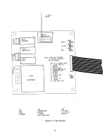
Page 38: ...30 Figure 51 Power Board...
Page 39: ...31 Figure 52 Program Module...
Page 54: ...46...
Page 66: ...58...
Page 68: ...60...
Page 69: ...61 666786...
Page 70: ...62...
Page 71: ...63...
Page 72: ...64...
Page 73: ...65...
Page 74: ...66...
Page 75: ...67...
Page 76: ...68...
Page 77: ...69...
Page 78: ...70...
Page 80: ......

