29
SECTION 5
CONTROLS
5.1
CONTROL SYSTEM TYPE 4
The control system is the brain of the freezer. To
understand how to service the freezer, it is essential to
understand how the control system operates. The Type
4 control is a consistency control and a temperature
control. To change functions, it is necessary to cut one
diode.
The control system when placed in the consistency
mode monitors the consistency (firmness) of the product
(mix) in the freezer evaporator. As the product freezes,
the drive motor develops a higher torque (resistance)
because of the freezing of the product in the evaporator.
The energy used to operate the drive motor is in direct
proportion to the torque. As the drive motor torque
increase, so does the energy required to operate the
motor. The program module senses the energy usage
and shuts off the drive motor when the preprogrammed
energy value is reached. The freezer will remain OFF
until the temperature rises to the preset looking
temperature (barrel temperature), then start.
The control system, when placed in the temperature
mode, monitors the product temperature in the freezer
evaporator. When the product temperature increases,
the temperature sensor probe sends an electronic signal
to the temperature control, which signals the compressor
and drive motor to switch ON. When the temperature
control is satisfied, the compressor will stop, and
approximately 10 seconds later, the gearmotor will stop.
The control also contains a hopper temperature control
(separate hopper refrigeration system only) and liquid
level indicator to monitor the mix temperature and level
in the hopper. When servicing a freezer in the consistency
mode, keep in mind the control system monitors product
consistency. To minimize the beating of product in the
evaporator, the program module will switch to the idle
mode after the preset number of consistency cycles are
complete. In the idle mode, the control is programmed to
maintain a preset hopper and barrel temperature. In this
idle mode, a servable consistency will not be held.
5.2
POWER BOARD
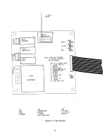
The power board is where the actual sensing of the drive
motor energy usage occurs. The power board also
supplies energy to the program module and sends
electronic signals associated with the drive motor
sensing. The 115 or 230/12 volt transformer and
associated circuitry are used to supply D.C. voltages to
operate the program module. There are two relays to
transfer power to the compressor and drive motor
contactors. The power board has a third relay; it is used
to transfer power to control the liquid line solenoid valve.
The relay will close after 2 hours of red light idle causing
the solenoid to open. There are four L.E.D.’s to monitor
the board’s operation. One L.E.D. indicates power to the
board. Two, three, and four indicate when the relays are
active.
5.3
PROGRAM MODULE
The program module is a multifunction control. It can
control product consistency or product temperature in
the barrel, mix temperature in the hopper, and indicate
mix level in the hopper. The board can be programmed
to control the functions of various freezers producing
many different products. To properly program the board,
it is necessary to understand the purpose of each
indicator light, switch, potentiometer, jumper, and the
liquid crystal display.
A. Indicator Lights
1.
The Power On indicator light, when illuminated
indicates the program module is receiving D.C.
power from the power board.
2.
The HPR light, when illuminated, indicates
power is available at J7 to control a separate
refrigeration system.
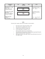
B. Liquid Crystal Display
1.
In the calibration mode, abbreviated word
indicators will be displayed indicating the control
function and set points being calibrated.
a.
TM-On Time
b.
STB-Stand-By Product Temperature
c.
CRS-Auger Drive Motor Current (amps)
d.
MTR-Motor Slope Adjustment
e.
SRV-Product Temperature
f.
HPR-Hopper Temperature
g.
LKG-Temp. set point in RDY
mode.
2.
In the operating mode, an abbreviated work
indicator will be displayed indicating the
operating function.
a.
DRV-Drive Motor
b.
CMP-Compressor
c.
LKG-Consistency
d.
CLN-Clean
Summary of Contents for E131G
Page 1: ...Model E131G F131G SERVICE MANUAL Manual No 513537 3 Mar 2004...
Page 2: ......
Page 14: ...6...
Page 38: ...30 Figure 51 Power Board...
Page 39: ...31 Figure 52 Program Module...
Page 54: ...46...
Page 66: ...58...
Page 68: ...60...
Page 69: ...61 666786...
Page 70: ...62...
Page 71: ...63...
Page 72: ...64...
Page 73: ...65...
Page 74: ...66...
Page 75: ...67...
Page 76: ...68...
Page 77: ...69...
Page 78: ...70...
Page 80: ......

