37
5.6
SPIGOT SWITCHES
The spigot switch will automatically actuate the auger
drive and refrigeration system when the spigot is opened
to dispense product. When the spigot is closed, the drive
motor and compressor will remain on until the product in
the barrel reaches the proper consistency.
5.7
SPIGOT SWITCH REMOVAL
To remove a spigot switch, perform the following
procedures:
WARNING
DISCONNECT FREEZER FROM ELECTRICAL
SUPPLY SOURCE BEFORE SERVICING.
1. Remove the two Phillips head screws from the bottom
of the decorative panel and slide the panel down and
out.
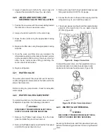
2. Remove the dispense rate adjuster knob located
below the header panel. Then remove the two Phillips
head screws that retain the handle assembly. Then
remove from the electrical box to access the switch
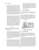
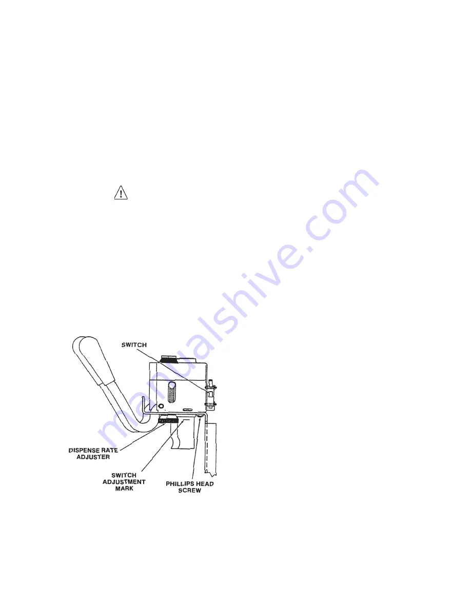
(Figure 55).
3. Disconnect the electrical wires and remove the switch
by removing the two retaining screws, nuts, and
washers.
Figure 55. Spigot Switch Replacement
5.8
SPIGOT SWITCH INSTALLATION
1. Install the replacement switch onto the handle
assembly. Do not fully tighten the retaining screws
at this time.
2. Using a pencil, mark the white plastic actuator ¼”
below the stainless steel housing. Adjust the switch
to activate when the spigot handle moves the plastic
piece to the mark. Then, fully tighten the retaining
screws (Figure 55).
3. Attach the electrical wires to the common (COM)
and normally open (N.O.) terminals on the spigot
switch.
4. Position the spigot handle assembly in the electrical
box and fasten securely with the two Phillips head
screws.
5. Replace the dispense rate adjuster knob and tighten.
6. Replace the decorative header panel and secure with
the two Phillips head screws.
5.9
FRONT DOOR INTERLOCK
SWITCH
When the door is securely fastened, the freezer will
operate normally. When the door is removed, the drive
and compressor will not run.
5.10
FRONT DOOR INTERLOCK
SWITCH REMOVAL
1. Remove the front door assembly.
2. Remove the two Phillips head screws from the bottom
of the decorative header panel and slide the panel
down and out.
3. Remove the dispense rate adjuster knob from the
right and center spigot handle assemblies.
4. Remove the two Phillips head screws from the spigot
handle assemblies located below the header panel,
then remove the handle assemblies.
Summary of Contents for E131G
Page 1: ...Model E131G F131G SERVICE MANUAL Manual No 513537 3 Mar 2004...
Page 2: ......
Page 14: ...6...
Page 38: ...30 Figure 51 Power Board...
Page 39: ...31 Figure 52 Program Module...
Page 54: ...46...
Page 66: ...58...
Page 68: ...60...
Page 69: ...61 666786...
Page 70: ...62...
Page 71: ...63...
Page 72: ...64...
Page 73: ...65...
Page 74: ...66...
Page 75: ...67...
Page 76: ...68...
Page 77: ...69...
Page 78: ...70...
Page 80: ......

