45
CAUTION
IF ACID HAS BEEN FOUND IN THE
COMPRESSOR SYSTEM. CLEAN OUT PER
THE COMPRESSOR MANUFACTURER’S
INSTRUCTIONS.
2. Remove all plugs from the replacement compressor.
3. Install any access fittings and the four rubber
compressor mounts on the replacement compressor.
4. Install the replacement compressor into the freezer
fitting the base over the four studs.
5. Install the four washers and nuts onto the studs and
tighten securely.
6. Leaving the port open to prevent pressure buildup,
braze the suction and discharge line to the
compressor.
7. Connect the wires in the compressor electrical box
and install the electrical box cover.
8. Purge and evacuate the refrigeration system to 50
microns of mercury for approximately 30 minutes.
9. Break the vacuum to (0 P.S.I.G.) through the low side
Schrader valve with dry nitrogen.
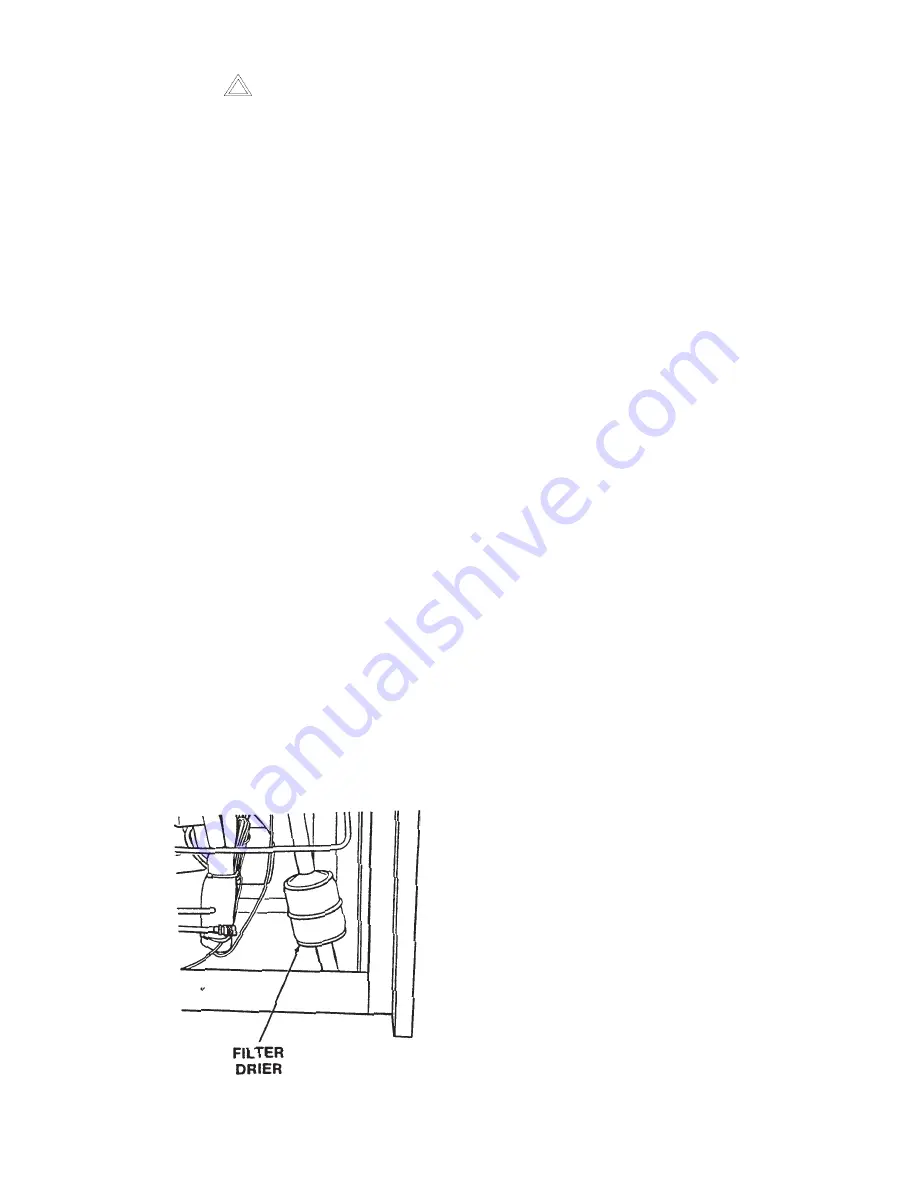
10.Remove the old filter drier and install a new filter
drier using the appropriate brazing material (Figure
75).
Figure 75. Filter Drier
11.Purge and evacuate the refrigeration system to 50
microns of mercury for approximately 30 minutes.
12.Accurately charge the system with R22 per the
amount indicated on the specification tag located on
the top front of the right side panel.
13.Leak check all fittings and connections.
14.Replace the 6” of insulating tubing to the suction line.
5.31
FINAL ASSEMBLY OF FREEZER
Upon completion of the removal and installation of any
or all of the major components of the freezer, the panels
must be replaced by performing the following procedures:
1. Position the back panel into place and install the two
Phillips head screws through the back panel and
tighten securely.
2. Position the right side panel (with nameplate) into
place and install the Phillips head screw through the
bottom of the side panel and tighten securely.
3. Position the left side panel into place and install the
Phillips head screw through the bottom of the side
panel and tighten securely.
4. Position the front panel into place and install the two
Phillips head screws through the bottom of the front
panel and tighten securely.
5. The freezer electrical supply can now be connected.
Summary of Contents for E131G
Page 1: ...Model E131G F131G SERVICE MANUAL Manual No 513537 3 Mar 2004...
Page 2: ......
Page 14: ...6...
Page 38: ...30 Figure 51 Power Board...
Page 39: ...31 Figure 52 Program Module...
Page 54: ...46...
Page 66: ...58...
Page 68: ...60...
Page 69: ...61 666786...
Page 70: ...62...
Page 71: ...63...
Page 72: ...64...
Page 73: ...65...
Page 74: ...66...
Page 75: ...67...
Page 76: ...68...
Page 77: ...69...
Page 78: ...70...
Page 80: ......


