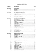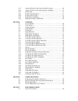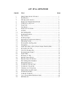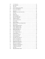
36
T.X.V. Removal ...................................................................................... 21
37
Bulb Installation ...................................................................................... 22
38
Filter Drier ............................................................................................... 22
39
E.P.R. Schrader Access Fitting .............................................................. 22
40
E.P.R. Valve Adjustment ........................................................................ 23
41
E.P.R. Valve and Lines ........................................................................... 24
42
Filter Drier ............................................................................................... 24
43
Capillary Tube and Drive Assembly ........................................................ 25
44
Filter Drier ............................................................................................... 25
45
Power Cord ............................................................................................ 25
46
Pressure Gauges ................................................................................... 26
47
Solenoid Replacement ............................................................................ 26
48
Solenoid Coil Removal ........................................................................... 26
49
Gauge Connection .................................................................................. 27
50
Water Valve Adjustment ......................................................................... 27
51
Power Board ........................................................................................... 30
52
Program Module ..................................................................................... 31
53
Membrane Switch Panel Display Board .................................................. 32
54
Plug-in Relays ........................................................................................ 36
55
Spigot Switch Replacement .................................................................... 37
56
Interlock Switch Removal ....................................................................... 38
57
Interlock Switch Assembly ...................................................................... 38
58
Switch Module Removal ......................................................................... 38
59
Electrical Box Removal ........................................................................... 39
60
Cover Plate Removal .............................................................................. 39
61
Foam Insulation Removal ....................................................................... 39
62
Ty-raps Removal .................................................................................... 40
63
Fan Motor Connections .......................................................................... 41
64
Fan Bracket Removal ............................................................................. 41
65
Drive Belt Removal ................................................................................. 42
66
Drive Motor Wire Removal ..................................................................... 42
67
Motor Pulley Adjustment ......................................................................... 42
68
Belt Tension Adjustment ......................................................................... 42
69
Speed Reducer Removal ........................................................................ 43
70
Speed Reducer Adjustment .................................................................... 43
71
Belt Tension Adjustment ......................................................................... 43
72
Compressor Cover Removal .................................................................. 44
73
Compressor Connections ....................................................................... 44
74
Compressor Oil Test Kit ......................................................................... 44
75
Filter Drier ............................................................................................... 45
76
O-Ring Identification Sheet ..................................................................... 59
Summary of Contents for E131G
Page 1: ...Model E131G F131G SERVICE MANUAL Manual No 513537 3 Mar 2004...
Page 2: ......
Page 14: ...6...
Page 38: ...30 Figure 51 Power Board...
Page 39: ...31 Figure 52 Program Module...
Page 54: ...46...
Page 66: ...58...
Page 68: ...60...
Page 69: ...61 666786...
Page 70: ...62...
Page 71: ...63...
Page 72: ...64...
Page 73: ...65...
Page 74: ...66...
Page 75: ...67...
Page 76: ...68...
Page 77: ...69...
Page 78: ...70...
Page 80: ......

