30
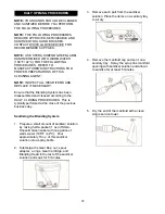
NOTE:
BE SURE TO PLACE A CONTAINER
UNDER THE BLENDING HEAD TO CATCH
THE PRODUCT AND SANITIZER SOLUTION.
NOTE:
YOUR HANDS SHOULD BE CLEANED
AND SANITIZED BEFORE YOU PERFORM
THE FOLLOWING PROCEDURE.
NOTE:
THE FOLLOWING PROCEDURES
REQUIRE APPROVED, SERVICEABLE AND
SANITIZED TOOLS AND BRUSHES.
CONTACT WHITE GLOVE SERVICE FOR
RECOMMENDED SUPPLIES.
NOTE:
USE STERA-SHEEN® GREEN LABEL
SANITIZER AND DAWN® DISH SOAP MIXED
WITH WARM WATER (108°F / 42°C) FOR THE
FOLLOWING PROCEDURES. REFER TO
MANUFACTURER’S INSTRUCTIONS FOR
PROPER PREPARATIONS OF THESE
CLEANING AGENTS.
NOTE:
INSPECT ALL WEAR ITEMS AND
REPLACE IF NECESSARY.
Each syrup flavor is stored inside a numbered
tray (1-4) within the system cabinet. Under
normal operating conditions, flavors are
installed as previous flavors become empty.
However, you may change flavors periodically
as desired.
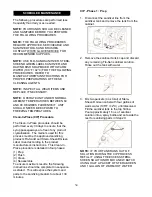
1. Prepare detergent water by mixing several
drops of Dawn
®
dish soap with a gallon of
warm water (108°F / 42°C). Prepare
sanitizer solution by mixing half a packet (1
oz) of Stera-Sheen® Green Label with one
gallon of warm water (108°F / 42°C) until
dissolved. Pour approximately 16 oz. of
sanitizer solution into a spray bottle and set
aside the rest.
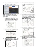
2. Place a cup or container under the spout.
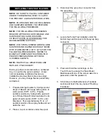
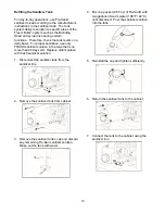
3. Disconnect the syrup line connector from
the syrup bag.
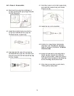
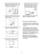
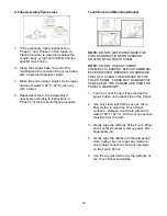
4. Locate the Pump Flush Adapter under the
bottom trays and connect it to the syrup bag
connector.
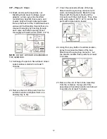
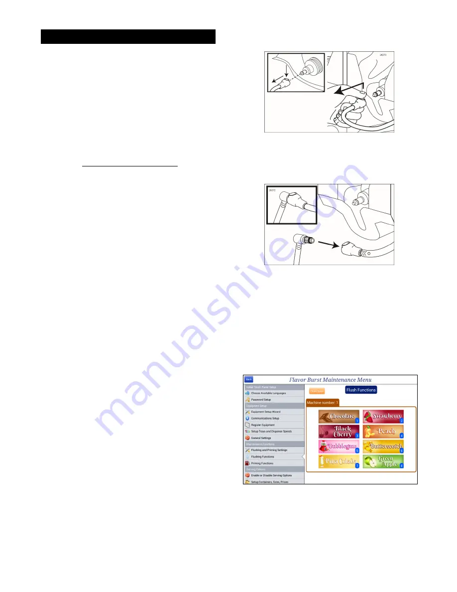
5. Press and hold the center logo on the
Touch Panel to access the Flavor Burst
Maintenance Menu. If the screen asks for a
password, enter the password.
6. Scroll down to the Maintenance Functions
section and touch the key named “Flushing
Functions”.
REPLACING THE SYRUP FLAVORS
Summary of Contents for Flavor Burst
Page 2: ......
Page 9: ...6 PAGE INTENTIONALLY LEFT BLANK...
Page 11: ...8 General System Overview Figure 1...
Page 13: ...10 Integrated Cabinet Continued Figure 2...
Page 17: ...14 Syrup Pump and Related Parts Figure 4...
Page 19: ...16 Sanitizer Pump and Related Parts Figure 5...
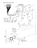
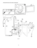
Page 21: ...18 Electronic Parts and Connections Continued Figure 6...
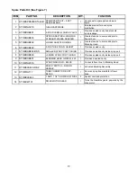
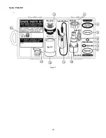
Page 23: ...20 Spare Parts Kit Figure 7...
Page 24: ...21 PAGE INTENTIONALLY LEFT BLANK...
Page 36: ...33 PAGE INTENTIONALLY LEFT BLANK...
Page 50: ...47 PAGE INTENTIONALLY LEFT BLANK...
Page 75: ......
Page 76: ......

