56
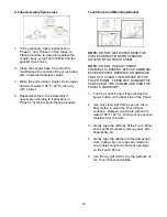
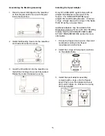
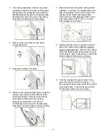
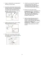
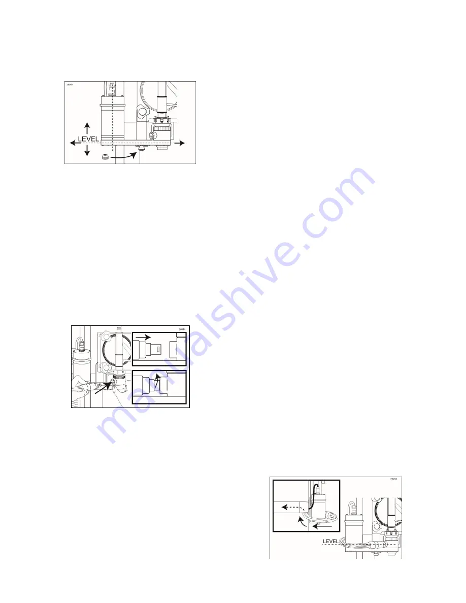
12. Ensure that the Gear Box of the Blending
Assembly is level horizontally and the Drive
Motor is straight vertically as it rests on the
bracket. Install the thumb nut and tighten to
secure the assembly’s position.
NOTE:
THE SUSPENSION BRACKET
SHOULD BE POSITIONED ON THE GEAR
BOX DURING INITIAL SET-UP AND DOES
NOT NEED TO BE REMOVED DURING
OPENING OR CLOSING PROCEDURES
UNLESS IT REQUIRES A MORE THOROUGH
CLEANING. THE SUSPENSION BRACKET
SHOULD BE CLEANED AT LEAST EVERY 30
DAYS, EITHER WHEN CLEAN-IN-PLACE
PROCEDURE IS PERFORMED AND/OR
WHEN THE FREEZER DOOR IS REMOVED
FOR CLEANING.
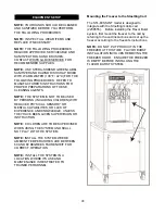
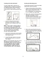
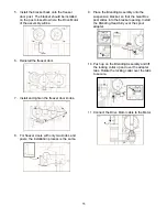
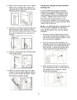
13. Insert the syrup line manifold end fully into
the Blending Head syrup line opening.
Rotate it until motion stops to secure.
Mounting the Tube / Cable Casing
Assemblies
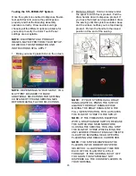
The STL-80BLD-INT includes two tube / cable
casing assemblies. The magnetic metal casing
assembly is designed to cover and hold the 9-
Tube Assembly level with the Blending
Assembly. It also channels the tubes, the Drive
Motor cable, and the Touch Panel ethernet
cable back to the rear of the freezer. The
smaller, black plastic casing is for channeling
the Touch Panel ethernet cable and draw
switch cable down the side of the freezer, to the
metal casing.
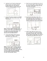
The following instructions and illustrations show
a left-side mounting, but right-side mounting is
possible when the Blending Assembly is
installed on the right.
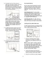
1. Prepare detergent water by mixing several
drops of Dawn
®
dish soap with a gallon of
warm water (108°F / 42°C).
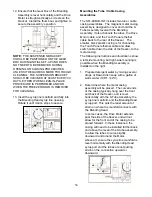
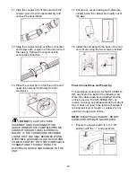
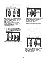
2. Determine where the metal casing
assembly will be placed. The curved ends
of the casing typically hang over the front
and back of the freezer, and is level
horizontally with the 9-Tube Assembly, the
syrup line manifold, and the Blending Head
syrup port. This puts the least amount of
strain on where the manifold connects with
the Blending Head.
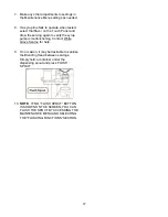
In some cases, the Drive Motor extends
past the side of the freezer and will not
allow for the front end of the casing to be
placed forward. In these instances, the
casing will need to be installed further back,
and above the level of the 9-tube assembly,
to allow the tubes to curve slightly
downward and around the Motor.
Above all, ensure the syrup line manifold is
level horizontally with the Blending Head
syrup port and the tubes are not putting
strain on the connection upward or
downward.
Summary of Contents for Flavor Burst
Page 2: ......
Page 9: ...6 PAGE INTENTIONALLY LEFT BLANK...
Page 11: ...8 General System Overview Figure 1...
Page 13: ...10 Integrated Cabinet Continued Figure 2...
Page 17: ...14 Syrup Pump and Related Parts Figure 4...
Page 19: ...16 Sanitizer Pump and Related Parts Figure 5...
Page 21: ...18 Electronic Parts and Connections Continued Figure 6...
Page 23: ...20 Spare Parts Kit Figure 7...
Page 24: ...21 PAGE INTENTIONALLY LEFT BLANK...
Page 36: ...33 PAGE INTENTIONALLY LEFT BLANK...
Page 50: ...47 PAGE INTENTIONALLY LEFT BLANK...
Page 75: ......
Page 76: ......


