22
H.
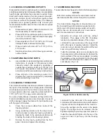
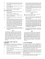
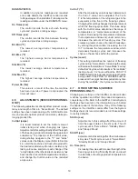
Feed one end of the mix pump hose into the
pickup hose side (left) of the black cover.
NOTE
Feed the tube into the clamp so the natural curve of
the tube is towards the outside of the black cover.
This prevents the hose from looping around the
black cover twice.
I.
Gently push the hose into the black cover until it
begins to feed.
J.
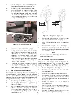
Allow the hose to feed itself through the pump
until about 6” (15cm) remains on the entering
side.
K.
Turn pump off.
L.
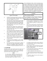
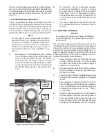
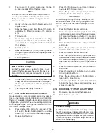
Connect the mix pump hose to the elbow fi tting
(located on the left side of the mix line manifold)
using a small hose clamp. Be careful not to twist
the mix hose.
M.
Turn the pump on.
N.
Allow the remaining 6” (15cm) of tubing to feed
through the pump until the hose adapter prevents
further feeding.
O.
Turn the pump off.
CAUTION
Risk of Product Damage
Air/Mix Tee must remain below the black cover
clamp. If the Tee is above the pump, the mix may
drain into the air compressor, resulting in pump
damage.
P.
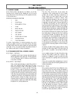
Connect the free end of the mix pump hose to the
3-way Tee. When all connections are complete,
the 3-way Tee must be lower than the black pump
housing.
Q.
The pump is now ready to sanitize.
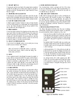
4.11 CAB
TEMPERATURE
ADJUSTMENT
Cab temperature is monitored and controlled by two set-
tings on the IntelliTec control: CabCutIn and CabCtOut.
The cut in value determines the temperature at which the
refrigeration cycle starts. The cut out setting determines
when the cycle stops. To change the CabCutIn or CabC-
tOut, follow the steps below:
A.
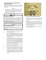
Press and hold SEL button for 8 seconds. While
still holding the SEL button, press the up arrow
button (
). The LCD Screen will read "Display".
B.
Release both buttons.
C.
Press the left arrow button (
) three (3) times to
navigate to the Storage menu.
D.
Press the up arrow button (
) once to navigate
to the CabCutIn value. Record this value.
IMPORTANT:
Before making changes to any settings, record
the original values. If the setting changes do not
achieve desired results, return settings to their
original values.
E.
Press SET button to enter edit mode.
F.
Press the up arrow button (
) to increase the
number to the value required. The value increases
by 1 each time the up arrow button (
) is pressed.
After the value reaches 9, numbering restarts at
0.
G.
Press SET button to save the setting and exit the
edit mode.
H.
Press the up arrow button (
) once to navigate
to the CabCtOut value. Record this value.
I.
Press SET button to enter edit mode.
J.
Press the up arrow button (
) to increase the
number to the value required. The value increases
by 1 each time the up arrow button (
) is pressed.
After the value reaches 9, numbering restarts at
0.
K.
Press SET button to save the setting and exit the
edit mode.
L.
Press the up arrow (
) and left arrow (
) buttons
to navigate to ExitMenu.
M.
Press the up arrow button (
) from ExitMenu to
return to the Mode Screen.
N. Locate
the
Specifi cation Sheet for SU412 Control
behind the header panel and record the new
values on this sheet.
4.12
DRIVE BELT TENSION ADJUSTMENT
A.
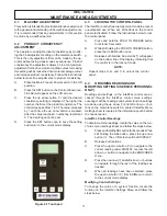
Remove a side panel and the back panel.
B. Press
fi rmly on one belt.
WARNING
Hazardous Voltage
The Main Freezer Power switch must be placed in
the OFF position when disassembling for servicing.
The machine must be disconnected from electrical
supply before removing any access panel. Failure
to disconnect power before servicing could result
in death or serious injury.

